Interactive Voice Response Network Diagram


"Network planning and design is an iterative process, encompassing topological design, network-synthesis, and network-realization, and is aimed at ensuring that a new telecommunications network or service meets the needs of the subscriber and operator. Network planning process involves three main steps: 1) Topological design: This stage involves determining where to place the components and how to connect them. 2) Network-synthesis: This stage involves determining the size of the components used, subject to performance criteria such as the Grade of Service (GoS). 3) Network realization: This stage involves determining how to meet capacity requirements, and ensure reliability within the network." [Network planning and design. Wikipedia]
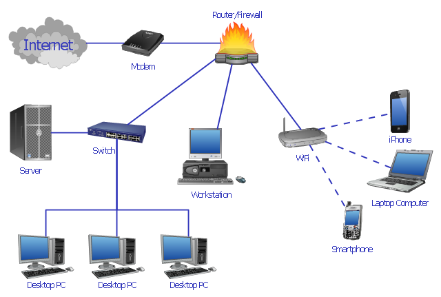
This computer network system design diagram example was created using the ConceptDraw PRO diagramming and vector drawing software extended with the Computer and Networks solution from the Computer and Networks area of ConceptDraw Solution Park.
This computer network system design diagram example was created using the ConceptDraw PRO diagramming and vector drawing software extended with the Computer and Networks solution from the Computer and Networks area of ConceptDraw Solution Park.
Network system design
"... logical topology shows how data flows within a network, regardless of its physical design. ...
... mapping the data flow between the components determines the logical topology of the network." [Network topology. Wikipedia]
"In a shared media topology, all the systems have the ability to access the physical layout whenever they need it. The main advantage in a shared media topology is that the systems have unrestricted access to the physical media. Of course, the main disadvantage to this topology is collisions. If two systems send information out on the wire at the same time, the packets collide and kill both packets. Ethernet is an example of a shared media topology. ...
The token-based topology works by using a token to provide access to the physical media. In a token-based network, there is a token that travels around the network. When a system needs to send out packets, it grabs the token off of the wire, attaches it to the packets that are sent, and sends it back out on the wire. As the token travels around the network, each system examines the token. When the packets arrive at the destination systems, those systems copy the information off of the wire and the token continues its journey until it gets back to the sender. When the sender receives the token back, it pulls the token off of the wire and sends out a new empty token to be used by the next machine." [Logical topology. Wikipedia]
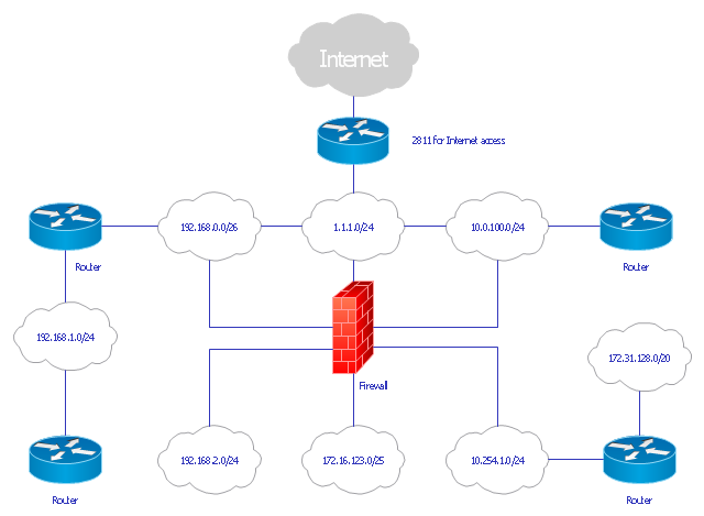
This Cisco logical computer network diagram example was created using the ConceptDraw PRO diagramming and vector drawing software extended with the Cisco Network Diagrams solution from the Computer and Networks area of ConceptDraw Solution Park.
... mapping the data flow between the components determines the logical topology of the network." [Network topology. Wikipedia]
"In a shared media topology, all the systems have the ability to access the physical layout whenever they need it. The main advantage in a shared media topology is that the systems have unrestricted access to the physical media. Of course, the main disadvantage to this topology is collisions. If two systems send information out on the wire at the same time, the packets collide and kill both packets. Ethernet is an example of a shared media topology. ...
The token-based topology works by using a token to provide access to the physical media. In a token-based network, there is a token that travels around the network. When a system needs to send out packets, it grabs the token off of the wire, attaches it to the packets that are sent, and sends it back out on the wire. As the token travels around the network, each system examines the token. When the packets arrive at the destination systems, those systems copy the information off of the wire and the token continues its journey until it gets back to the sender. When the sender receives the token back, it pulls the token off of the wire and sends out a new empty token to be used by the next machine." [Logical topology. Wikipedia]
This Cisco logical computer network diagram example was created using the ConceptDraw PRO diagramming and vector drawing software extended with the Cisco Network Diagrams solution from the Computer and Networks area of ConceptDraw Solution Park.
Logical network diagram
 Cisco Network Diagrams
Cisco Network Diagrams solution extends ConceptDraw PRO software with samples, templates and libraries of vector stencils for drawing the Cisco computer network diagrams.
"Fault-tolerant computer systems are systems designed around the concepts of fault tolerance. In essence, they have to be able to keep working to a level of satisfaction in the presence of faults. ...
Most fault-tolerant computer systems are designed to be able to handle several possible failures, including hardware-related faults such as hard disk failures, input or output device failures, or other temporary or permanent failures; software bugs and errors; interface errors between the hardware and software, including driver failures; operator errors, such as erroneous keystrokes, bad command sequences, or installing unexpected software; and physical damage or other flaws introduced to the system from an outside source." [Fault-tolerant computer system. Wikipedia]
The computer network diagram example "Cisco LAN fault-tolerance system" was created using the ConceptDraw PRO diagramming and vector drawing software extended with the Cisco Network Diagrams solution from the Computer and Networks area of ConceptDraw Solution Park.
LAN fault-tolerance system

Used Solutions
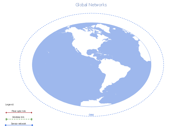
A conceptual diagram of a global vehicular network describes the principles of communication between vehicles, earth-based nodes, and space-based nodes in a wireless network. It illustrates the concept of architecture within global vehicular networks.
"Intelligent transportation systems (ITS) are advanced applications which, without embodying intelligence as such, aim to provide innovative services relating to different modes of transport and traffic management and enable various users to be better informed and make safer, more coordinated, and 'smarter' use of transport networks.
...
Intelligent transport systems vary in technologies applied, from basic management systems such as car navigation; traffic signal control systems; container management systems; variable message signs; automatic number plate recognition or speed cameras to monitor applications, such as security CCTV systems; and to more advanced applications that integrate live data and feedback from a number of other sources, such as parking guidance and information systems; weather information; bridge deicing systems; and the like." [Intelligent transportation system. Wikipedia]
The global vehicular network diagram template is included in the Vehicular Networking solution from the Computer and Networks area of ConceptDraw Solution Park.
Global vehicular network diagram template
How To use Switches in Network Diagram

 Computer and Networks Area
The solutions from Computer and Networks Area of ConceptDraw Solution Park collect samples, templates and vector stencils libraries for drawing computer and network diagrams, schemes and technical drawings.
Network Diagram Software Logical Network Diagram

- How to Draw a Computer Network Diagrams | Computer network ...
- Computer network system design diagram | How to Draw a ...
- How to Draw a Computer Network Diagrams | Computer network ...
- Interactive Voice Response Network Diagram | Telecommunication ...
- How to Draw a Computer Network Diagrams | Interactive Voice ...
- How to Draw a Computer Network Diagrams | Basic CCTV System ...
- How to Draw a Computer Network Diagrams | ConceptDraw PRO ...
- How to Draw a Computer Network Diagrams | Engineering ...
- Computer network system design diagram | Diagramming software ...
- Interactive Voice Response Network Diagram | Interactive Voice ...
- How to Draw a Computer Network Diagrams | Design Element: IVR ...
- CCTV Surveillance System Diagram. CCTV Network Diagram ...
- Computer network system design diagram | Network Diagramming ...
- How to Draw a Computer Network Diagrams | Network ...
- Data Flow Diagrams with ConceptDraw PRO | Interactive Voice ...
- How to Draw a Computer Network Diagrams | UML Diagrams with ...
- Cisco LAN fault-tolerance system - diagram | How to Draw a ...
- How to Draw a Computer Network Diagrams | UML Diagrams with ...
- How to Draw a Computer Network Diagrams | Network diagrams ...
- Network Diagram Software IVR Services