This interactive voice response (IVR) diagram sample depicts the architecture of IVR systems. It was designed on the base of the Wikimedia Commons file: IVR-Systemarchitektur.png. [commons.wikimedia.org/ wiki/ File:IVR-Systemarchitektur.png]
This file is licensed under the Creative Commons Attribution-Share Alike 3.0 Unported license. [creativecommons.org/ licenses/ by-sa/ 3.0/ deed.en]
"DTMF decoding and speech recognition are used to interpret the caller's response to voice prompts. DTMF tones are entered via the telephone keypad. ...
Other technologies include using text-to-speech (TTS) to speak complex and dynamic information, such as e-mails, news reports or weather information. TTS is computer generated synthesized speech that is no longer the robotic voice traditionally associated with computers. Real voices create the speech in fragments that are spliced together (concatenated) and smoothed before being played to the caller.
An IVR can be deployed in several ways:
1. Equipment installed on the customer premises.
2. Equipment installed in the PSTN (public switched telephone network).
3. Application service provider (ASP) / hosted IVR.
IVR can be used to provide a more sophisticated voice mail experience to the caller. ...
An automatic call distributor (ACD) is often the first point of contact when calling many larger businesses. ...
IVR call flows are created in a variety of ways. A traditional IVR depended upon proprietary programming or scripting languages, whereas modern IVR applications are generated in a similar way to Web pages, using standards such as VoiceXML, CCXML, SRGS and SSML. ...
In telecommunications, an audio response unit (ARU) is a device that provides synthesized voice responses to DTMF keypresses by processing calls based on (a) the call-originator input, (b) information received from a database, and (c) information in the incoming call, such as the time of day.
ARUs increase the number of information calls handled and provide consistent quality in information retrieval." [Interactive voice response. Wikipedia]
The IVR diagram example "IVR systems architecture" was designed using ConceptDraw PRO diagramming and vector drawing software extended with the Interactive Voice Response Diagrams solution from the Computer and Networks area of ConceptDraw Solution Park.
IVR diagram

 Azure Architecture
Azure Architecture solution bundles into one handy tool everything you need to create effective Azure Architecture diagrams. It adds the extra value to versatile ConceptDraw PRO software and extends the users capabilities with comprehensive collection of Microsoft Azure themed graphics, logos, preset templates, wide array of predesigned vector symbols that covers the subjects such as Azure management, Azure storage, and Azure services, amongst others, and allow you to illustrate Azure Architecture diagrams at any degree of complexity, to present visually your Azure cloud system architecture with professional style, to design Azure cloud topology, to document Windows Azure Architecture and Azure Cloud System Architecture, to visualize the great abilities and work of Microsoft Azure Cloud System and Azure services.
 AWS Architecture Diagrams
The flexible AWS cloud solutions will help you to create reliable applications with a high level of scaling in the AWS cloud, to run your applications and accelerate their work on the level of security. Besides AWS resources are available worldwide and yo
 ConceptDraw Solution Park
ConceptDraw Solution Park collects graphic extensions, examples and learning materials
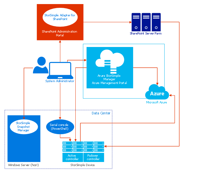
This example of cloud computing system architecture diagram was created on the base of picture in the article "What is StorSimple?" by Sharon Smith from the Microsoft Azure website.
"Microsoft Azure StorSimple is an efficient, cost-effective, and manageable solution that eliminates many of the issues and expense associated with enterprise storage and data protection. It uses a proprietary device (the Microsoft Azure StorSimple device) and integrated management tools to provide a seamless view of all enterprise storage, including cloud storage." [azure.microsoft.com/ en-us/ documentation/ articles/ storsimple-overview/ ]
The diagram example "Microsoft Azure StorSimple architecture" was created using ConceptDraw PRO diagramming and vector drawing software extended with the Azure Architecture solution from the Computer and Networks area of ConceptDraw Solution Park.
Cloud computing system architecture diagram
HelpDesk
How to Create an Azure Architecture Diagram Using ConceptDraw PRO

- Design elements - Enterprise architecture diagram | Lean ...
- Azure Storage | Microsoft Azure | Azure Architecture | Azure Blob Logo
- Design elements - Azure architecture - Microsoft products | Push ...
- IVR systems architecture | Basic Flowchart Symbols and Meaning ...
- Amazon Cloud Computing Architecture | Sequence Diagram for ...
- Azure Blob Storage Logo
- Cloud Computing Architecture Diagrams | Azure Architecture | AWS ...
- Azure Architecture | Windows Azure | How to Create an Azure ...
- Architecture Softwares Logos
- IVR Systems | IVR systems architecture | Interactive Voice Response ...
- Block diagram - Document management system architecture | Block ...
- Aws Emr Logo
- AWS Simple Icons for Architecture Diagrams
- Cloud Computing Architecture Diagrams | Introduction to Cloud ...
- Grid computing system architecture | Cisco IBM. Cisco icons, shapes ...
- Cloud Computing Architecture Diagrams | Cloud Computing ...
- IVR systems architecture | Call Forwarding with ENUM | IVR services ...
- Block diagram - Document management system architecture ...
- Azure Architecture | Microsoft Azure | Microsoft Azure reference ...
- System Diagrams For Computing