This SysML diagram example was redesigned from Wikimedia Commons file: Use case restaurant model.svg.
"Use case model of a restaurant business." [commons.wikimedia.org/ wiki/ File:Use_ case_ restaurant_ model.svg]
"The use case diagram describes the usage of a system (subject) by its actors (environment) to achieve a goal, that is
realized by the subject providing a set of services to selected actors. The use case can also be viewed as functionality and/
or capabilities that are accomplished through the interaction between the subject and its actors. Use case diagrams include the use case and actors and the associated communications between them. Actors represent classifier roles that are external to the system that may correspond to users, systems, and or other environmental entities. They may interact either directly or indirectly with the system. The actors are often specialized to represent a taxonomy of user types or external systems." [omg.org/ spec/ SysML/ 1.3/ ]
The SysML diagram example "Use case restaurant model" was drawn using the ConceptDraw PRO diagramming and vector drawing software extended with the SysML solution from the Software Development area of ConceptDraw Solution Park.
Example of SysML use case diagram

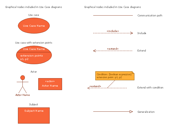
The vector stencils library "Use case diagram" contains 10 symbols.
Use it to design your use case diagrams using ConceptDraw PRO diagramming and vector drawing software.
"A use case diagram at its simplest is a representation of a user's interaction with the system that shows the relationship between the user and the different use cases in which the user is involved. A use case diagram can identify the different types of users of a system and the different use cases and will often be accompanied by other types of diagrams as well." [Use case diagram. Wikipedia]
The SysML symbols example "Design elements - Use case diagram" is included in the SysML solution from the Software Development area of ConceptDraw Solution Park.
SysML use case diagram symbols
 SYSML
SYSML
The SysML solution helps to present diagrams using Systems Modeling Language; a perfect tool for system engineering.
The vector stencils library "Use case diagram" contains 10 symbols.
Use it to design your use case diagrams using ConceptDraw PRO diagramming and vector drawing software.
"A use case diagram at its simplest is a representation of a user's interaction with the system that shows the relationship between the user and the different use cases in which the user is involved. A use case diagram can identify the different types of users of a system and the different use cases and will often be accompanied by other types of diagrams as well." [Use case diagram. Wikipedia]
The SysML symbols example "Design elements - Use case diagram" is included in the SysML solution from the Software Development area of ConceptDraw Solution Park.
Use it to design your use case diagrams using ConceptDraw PRO diagramming and vector drawing software.
"A use case diagram at its simplest is a representation of a user's interaction with the system that shows the relationship between the user and the different use cases in which the user is involved. A use case diagram can identify the different types of users of a system and the different use cases and will often be accompanied by other types of diagrams as well." [Use case diagram. Wikipedia]
The SysML symbols example "Design elements - Use case diagram" is included in the SysML solution from the Software Development area of ConceptDraw Solution Park.
SysML use case diagram symbols
SysML

Jacobson Use Cases Diagram

Systems Engineering

Model Based Systems Engineering

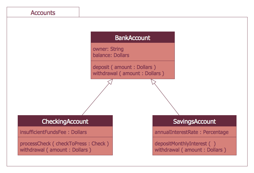
"In software and systems engineering, a use case is a list of steps, typically defining interactions between a role (known in Unified Modeling Language (UML) as an "actor") and a system, to achieve a goal. The actor can be a human or an external system.
In systems engineering, use cases are used at a higher level than within software engineering, often representing missions or stakeholder goals. The detailed requirements may then be captured in Systems Modeling Language (SysML) or as contractual statements.
As an important requirement technique, use cases have been widely used in modern software engineering over the last two decades. Use case driven development is a key characteristic of process models and frameworks like Unified Process (UP), Rational Unified Process (RUP), Oracle Unified Method (OUM), etc. With its iterative and evolutionary nature, use case is also a good fit for agile development." [Use case. Wikipedia]
The template "UML use case diagram" for the ConceptDraw PRO diagramming and vector drawing software is included in the Rapid UML solution from the Software Development area of ConceptDraw Solution Park.
www.conceptdraw.com/ solution-park/ software-uml
UML use case diagram

Bank System
- Use case restaurant model | Use Case Diagrams technology with ...
- Use Case Diagrams technology with ConceptDraw PRO | SYSML ...
- Jacobson Use Cases Diagram | Use case restaurant model | SYSML ...
- Use Case Diagrams technology with ConceptDraw PRO | Use case ...
- Use case restaurant model
- Event-driven Process Chain Diagrams | Rapid UML | SYSML | Use ...
- ATM UML Diagrams | Rapid UML | SYSML | Use Case Diagram Of A ...
- Use Case Diagram For Remote Computer Monitoring
- Jacobson Use Cases Diagram | Use case restaurant model | UML ...
- SysML Diagram | UML Use Case Diagram Example - Taxi Service ...