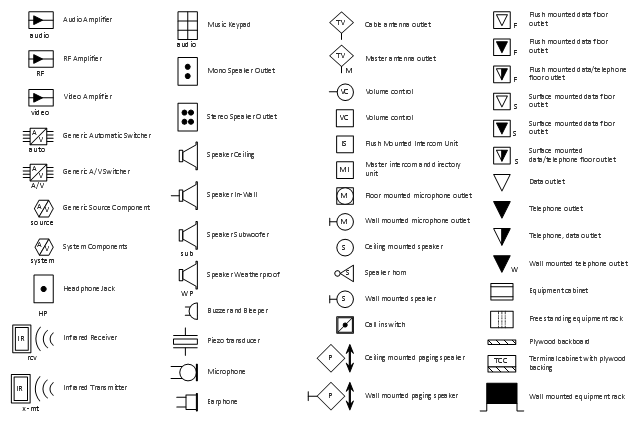
The vector stencils library "Video and audio" contains 50 symbols of audio and video devices and equipment.
Use the design elements library "Video and audio" for drawing audio and video system layouts, cabling floor plans, electrical circuit schematics and wiring diagrams of video and sound reproduction systems using the ConceptDraw PRO diagramming and vector drawing software.
Using the "Video and audio" library you can create video and audio engineering drawings and layout plans of your digital and analog, stereophonic (stereo), high fidelity (Hi-Fi, or hifi), quadraphonic, surround-sound, and home audio systems, home entertainment systems, home cinema (home theater, or home theatre), high-definition television (HDTV) and 3D television systems.
The shapes library "Video and audio" is included in the Electric and Telecom Plans solution from the Building Plans area of ConceptDraw Solution Park.
 Event-driven Process Chain Diagrams
Event-driven Process Chain (EPC) Diagram is a type of flowchart widely used for modeling in business engineering and reengineering, business process improvement, and analysis. EPC method was developed within the Architecture of Integrated Information Systems (ARIS) framework.
- Design elements - Qualifying | Entity Relationship Diagram Symbols ...
- Basic Flowchart Symbols and Meaning | Fire Exit Plan . Building Plan ...
- How To use House Electrical Plan Software | Electrical Drawing ...
- Lighting and switch layout | Lighting and switch layout | Design ...
- Electrical Drawing Software | How To use House Electrical Plan ...
- Design elements - Qualifying | Entity Relationship Diagram Symbols ...
- Signs And Symbols For Building Plan Drawings
- Design elements - Qualifying | Entity Relationship Diagram Symbols ...
- Basic Flowchart Symbols and Meaning | Design elements ...
- Entity Relationship Diagram Symbols and Meaning ERD Symbols ...
- Engineering Design Symbols And Their Meanings
- Chemical and Process Engineering | Basic Flowchart Symbols and ...
- Design elements - Qualifying | Process Flowchart | Basic Flowchart ...
- Electrical Installation Symbols And Signs
- Building Drawing Software for Design Office Layout Plan ...
- Electricity Plan Symbols And Meanings
- Electrical House Wiring Symbols And Meanings
- Electrical Diagram Symbols
- How To use House Electrical Plan Software | Entity Relationship ...
- Website Symbols Their Meanings
