Electrical Symbols — Switches and Relays

The vector stencils library "Hydraulic pumps and motors" contains 74 symbols of hydraulic equipment.
Use these shapes for engineering drawings of fluid power and hydraulic control systems in the ConceptDraw PRO diagramming and vector drawing software extended with the Mechanical Engineering solution from the Engineering area of ConceptDraw Solution Park.
www.conceptdraw.com/ solution-park/ engineering-mechanical
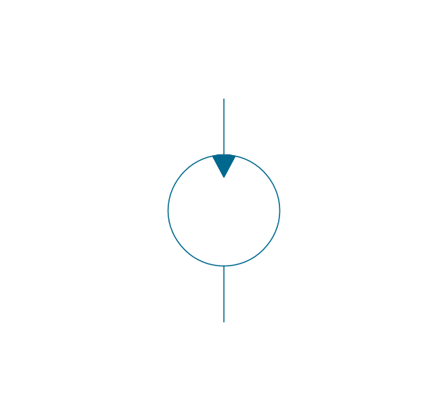
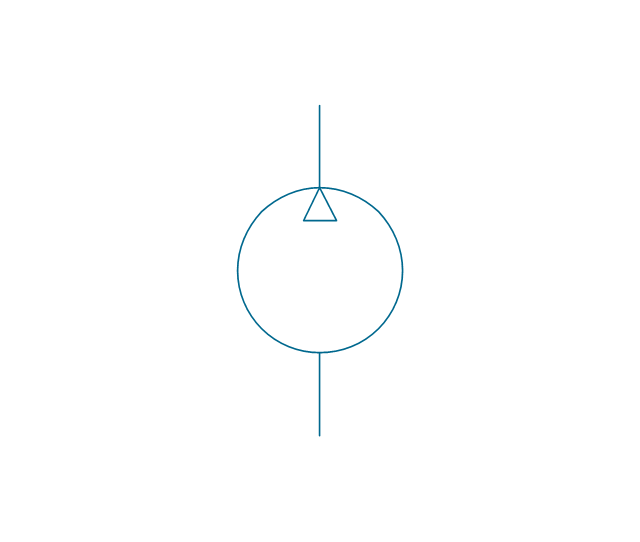
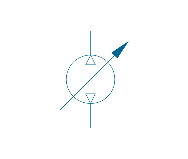
Pump, hydraulic

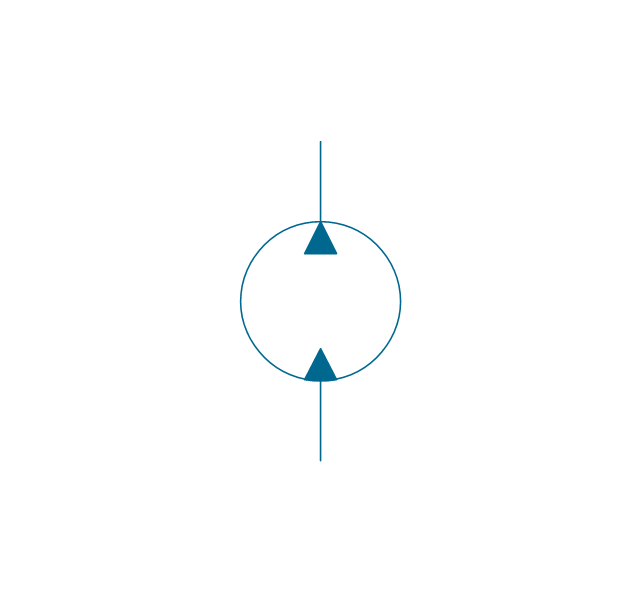
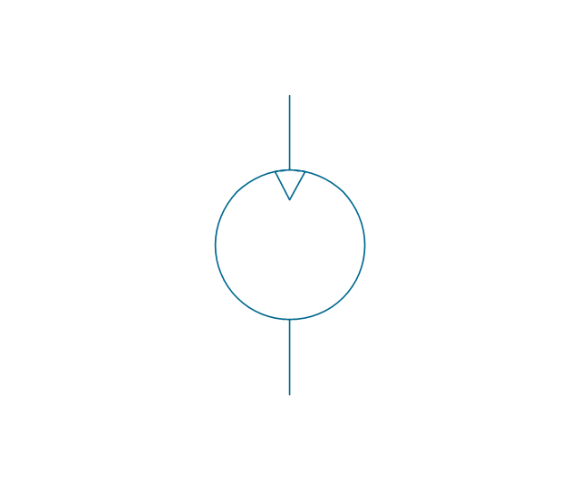
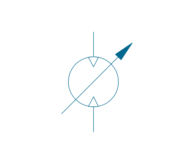
Motor, hydraulic
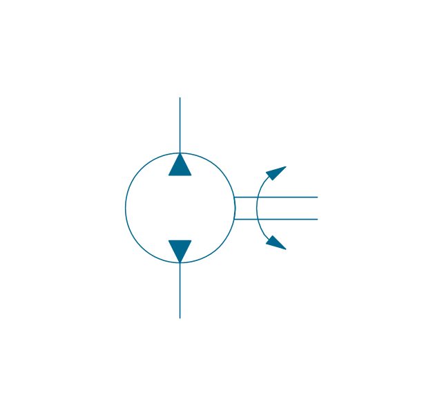
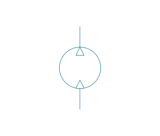
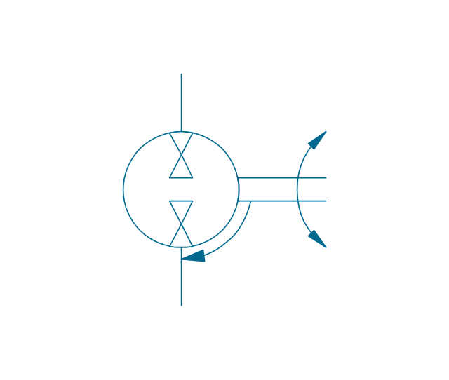
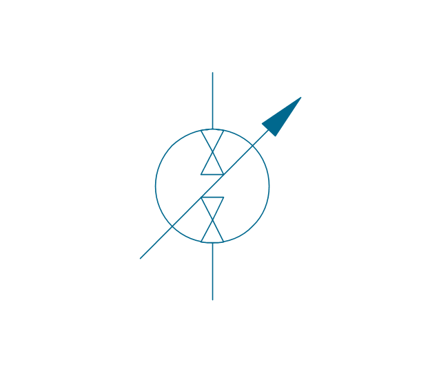
Pump-motor, hydraulic
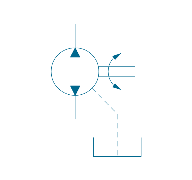
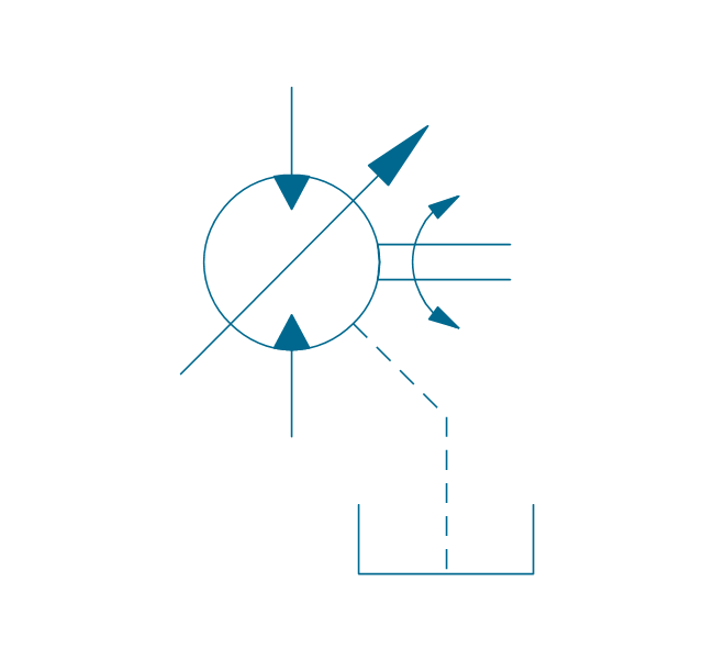
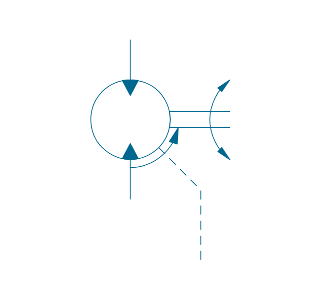
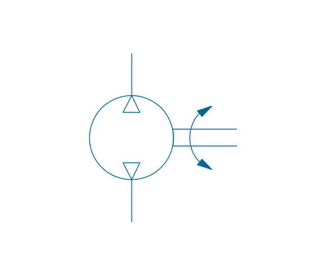
Pump, fixed, external drain
Pump, fixed, external drain
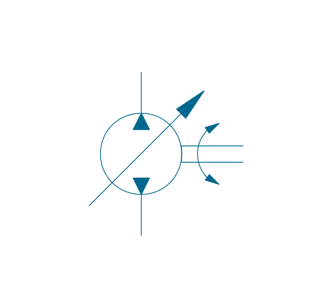
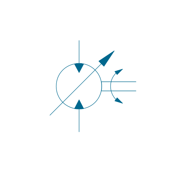
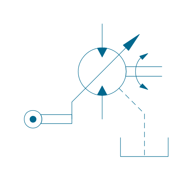
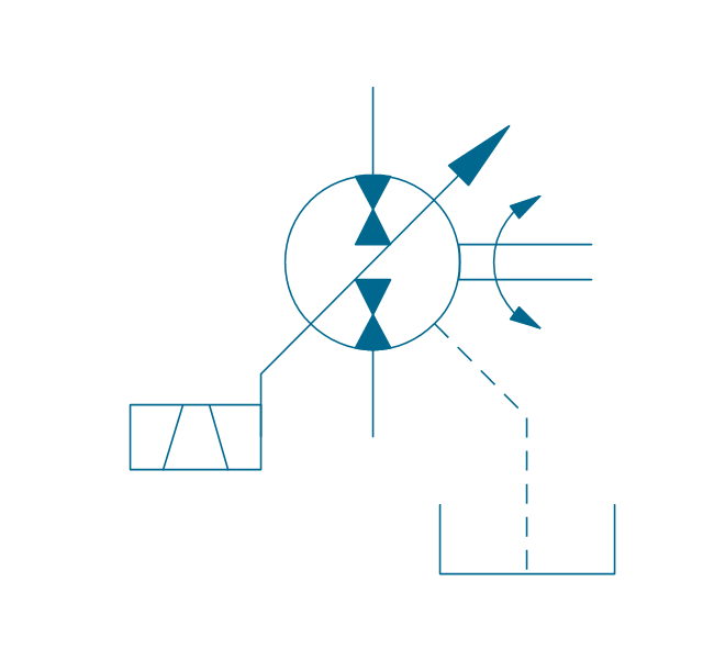
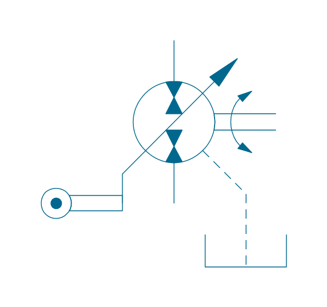
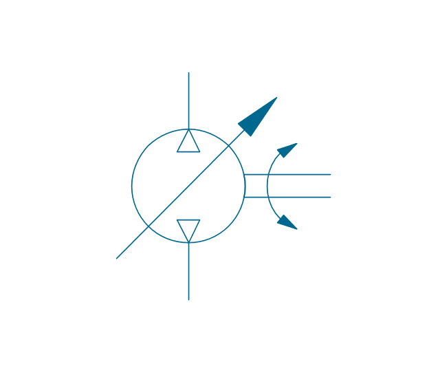
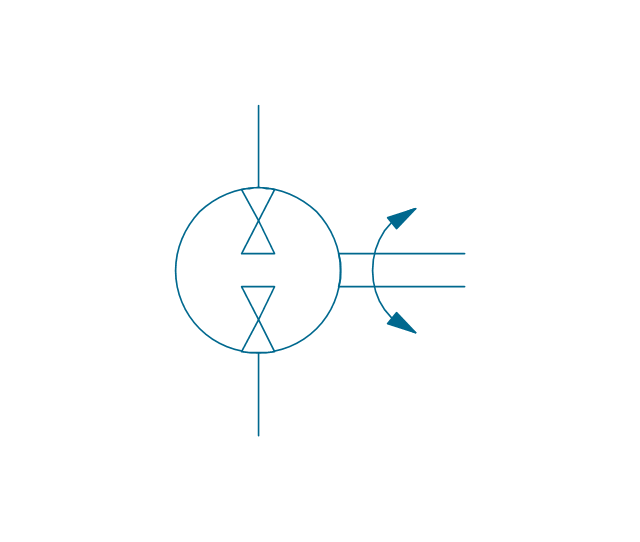
Pump, variable
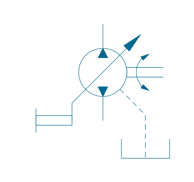
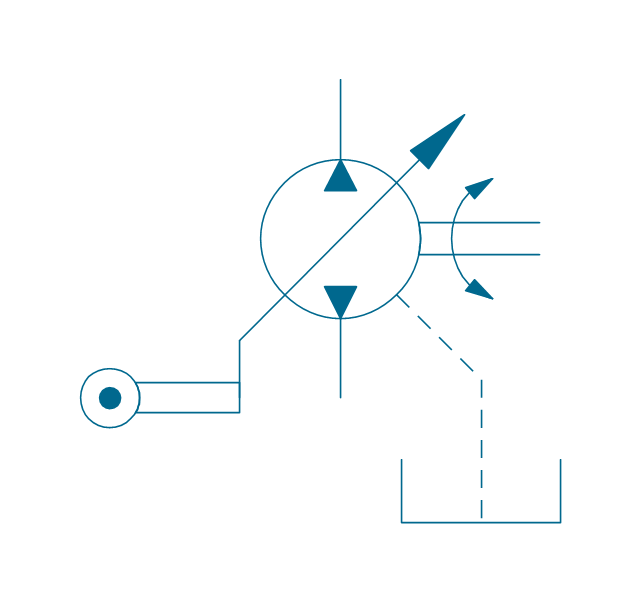
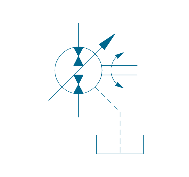
Pump, variable, external drain

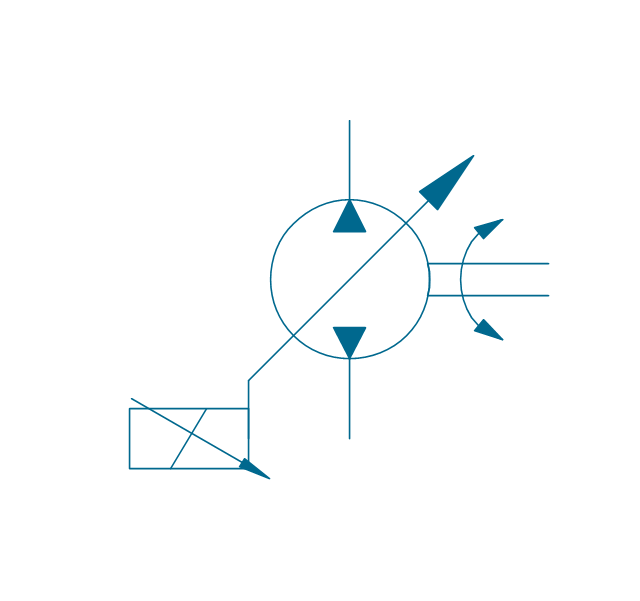
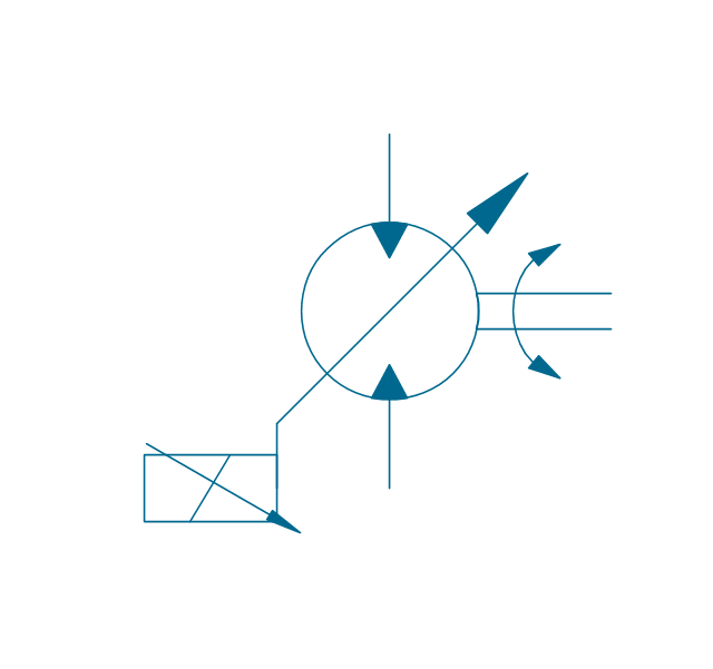
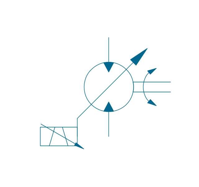
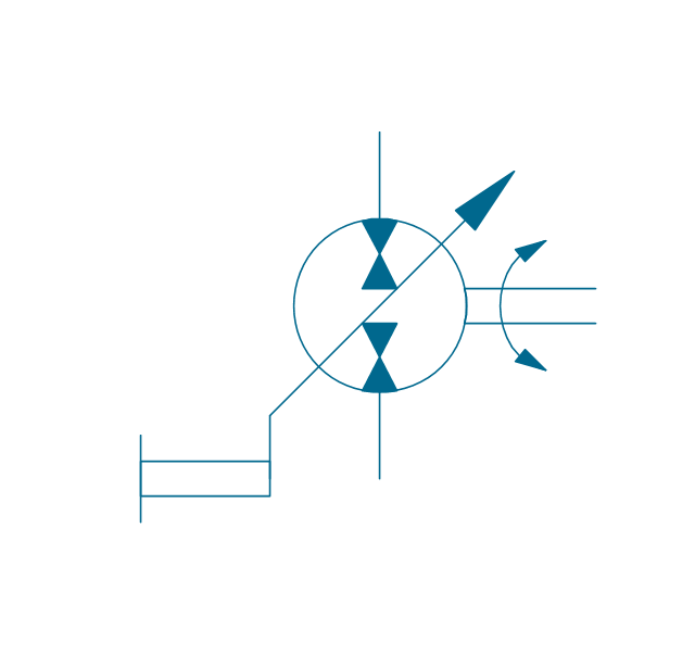
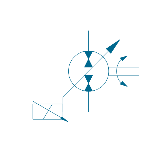
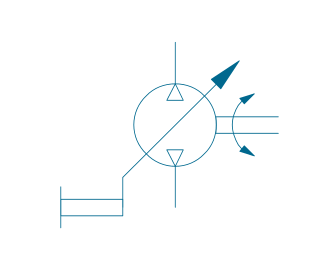
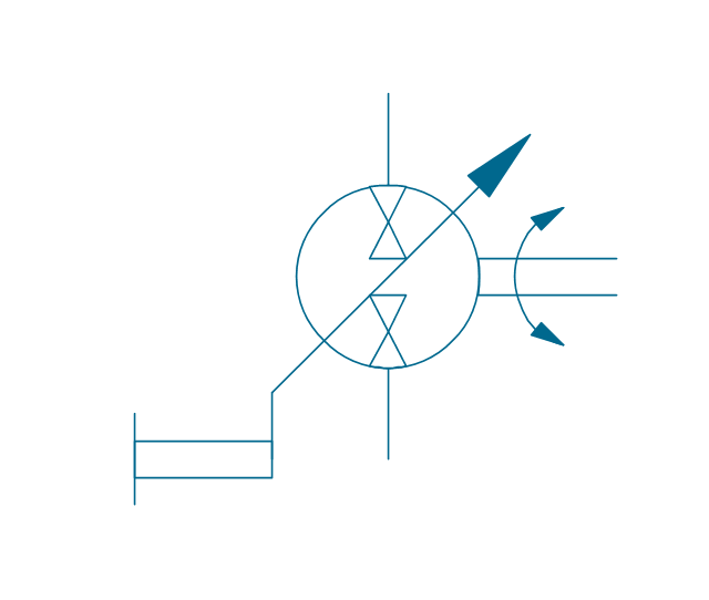
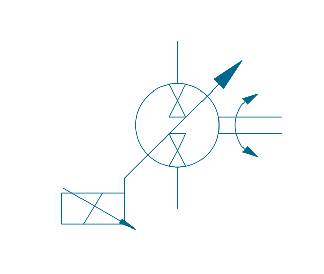
Pump, var., manual override

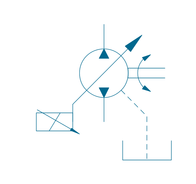
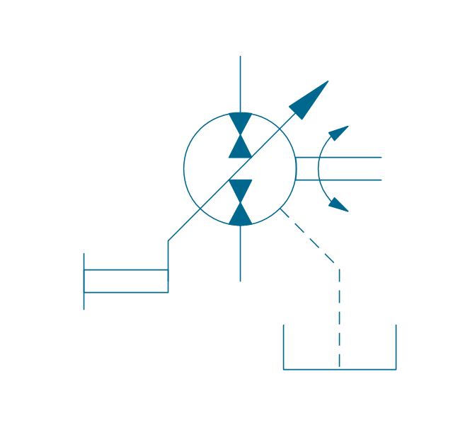
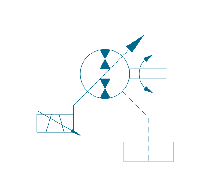
Pump, var., manual override, drain
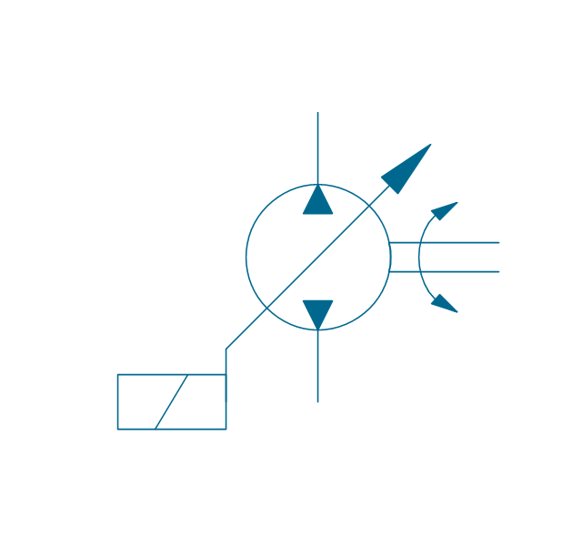
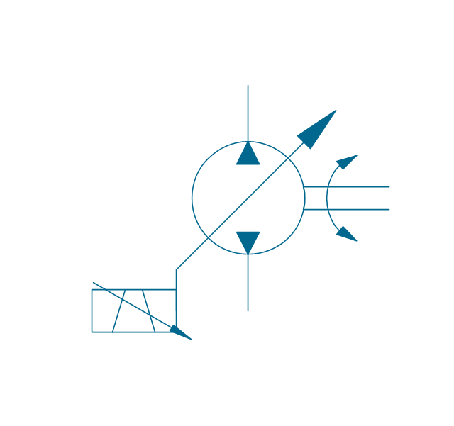
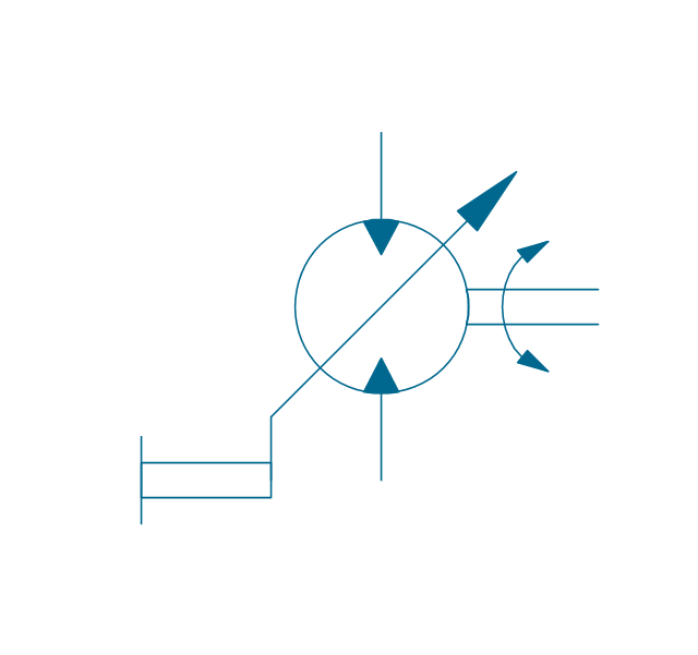
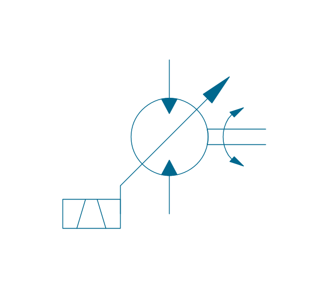
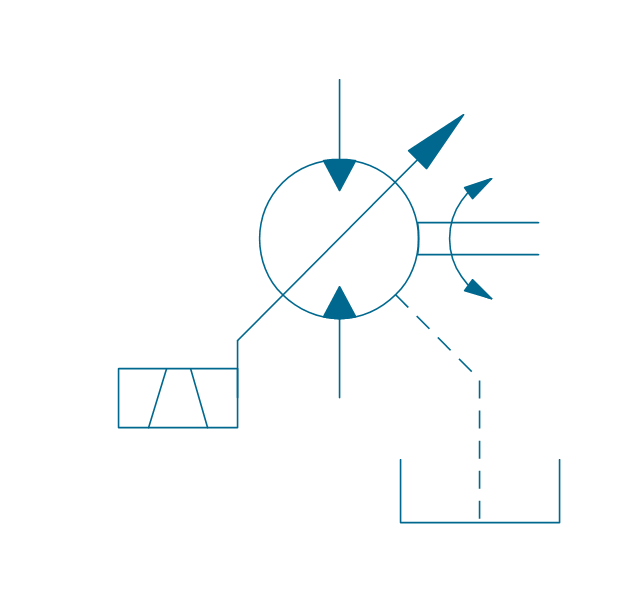
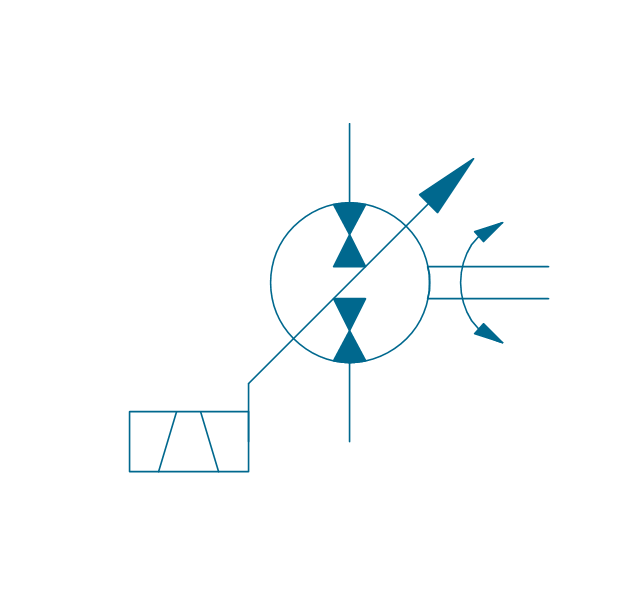
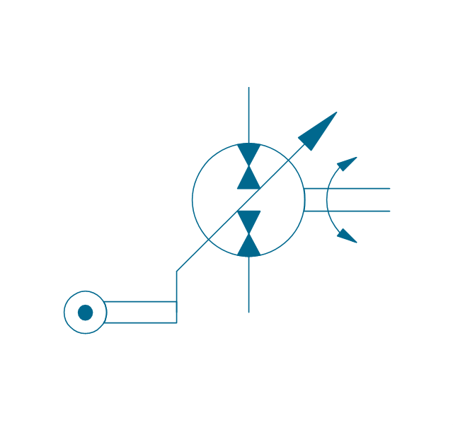
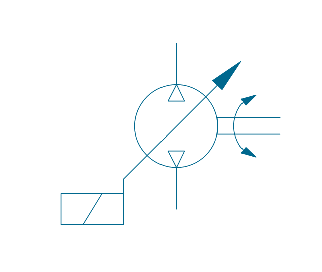
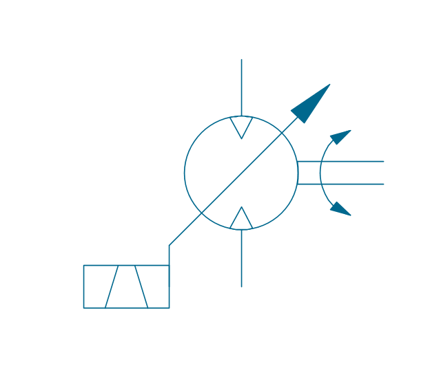
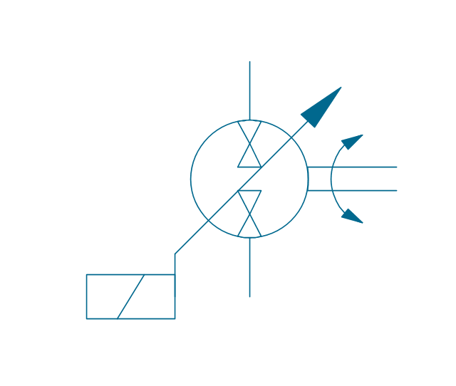
Pump, var., solenoid
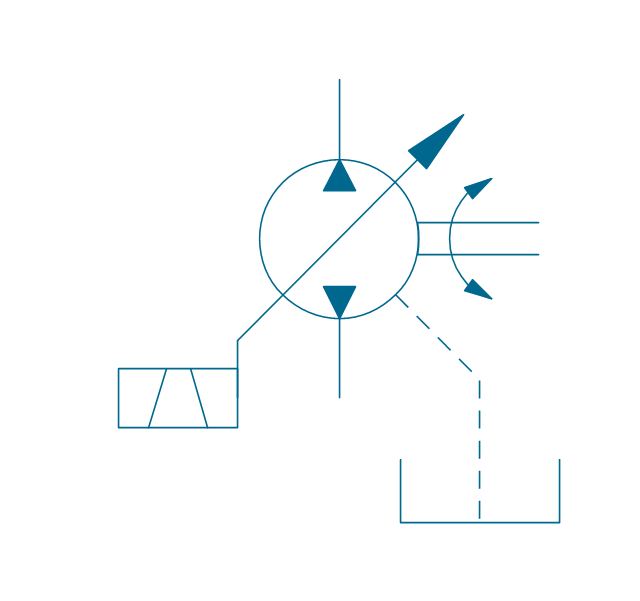
Pump, var., solenoid, drain

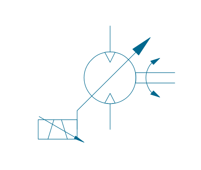
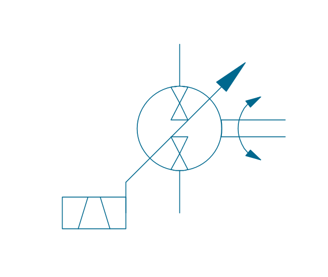
Pump, var., solenoid 2

Pump, var., solenoid 2, drain
Pump, var., var. solenoid
Pump, var., var. solenoid, drain
Pump, var., var. solenoid 2
Pump, var., var. solenoid 2, drain

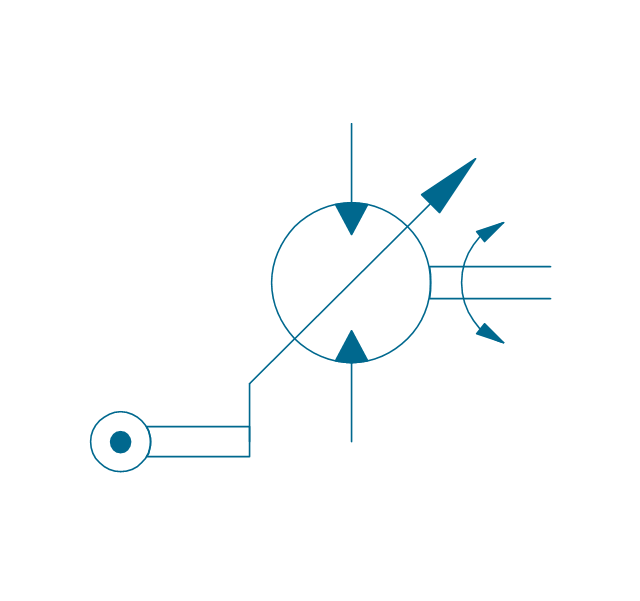
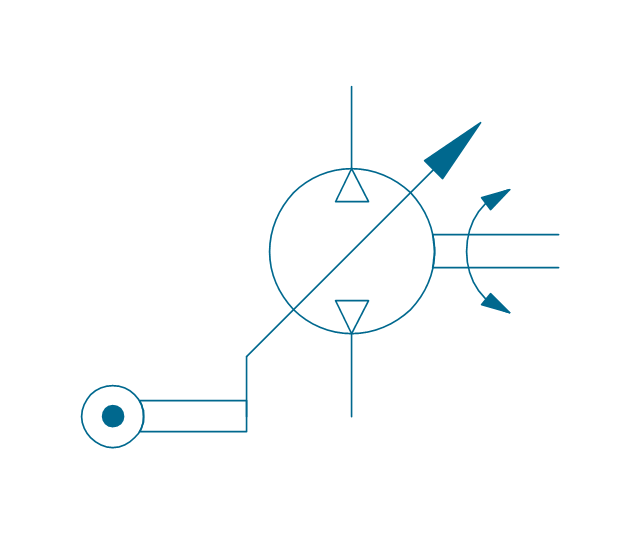
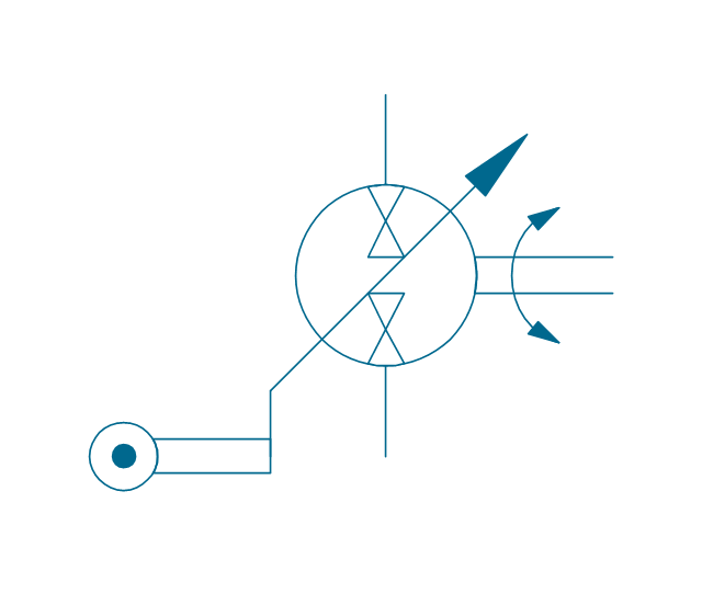
Pump, var., var., roller
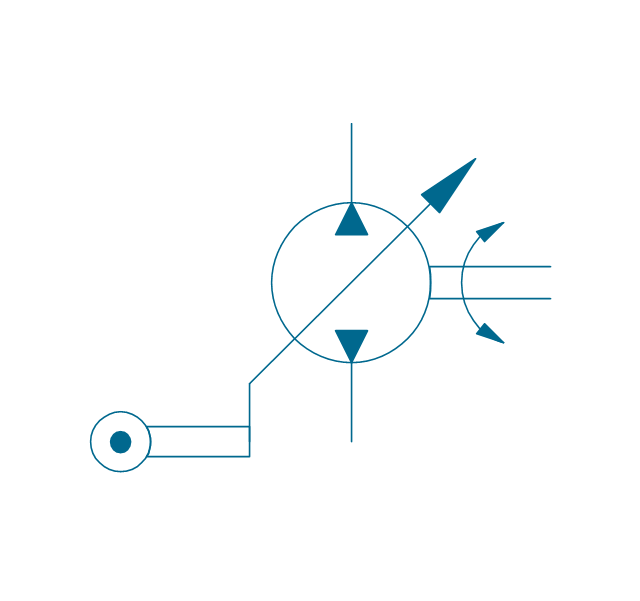
Pump, var., roller, drain
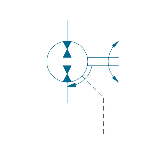
Motor, fixed, external drain
Motor, fixed, external drain
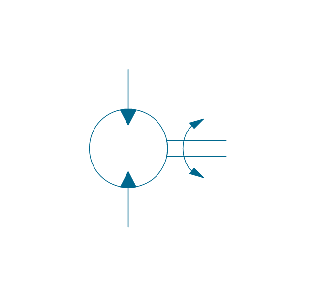
Motor, variable
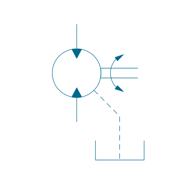
Motor, variable, external drain
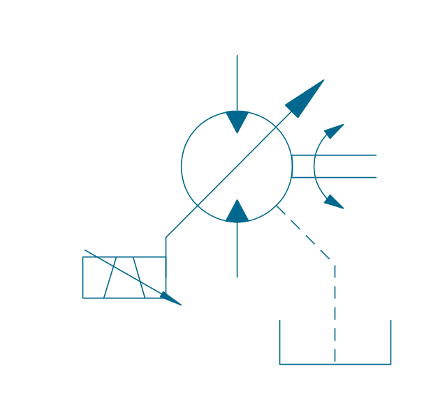
Motor, var., manual override
Motor, var., manual override, drain

Motor, var., solenoid

Motor, var., solenoid, drain

Motor, var., solenoid 2
Motor, var., solenoid 2, drain
Motor, var., var. solenoid
Motor, var., var. solenoid, drain

Motor, var., var. solenoid 2
Motor, var., var. solenoid 2, drain
Motor, var., var., roller
Motor, var., roller, drain
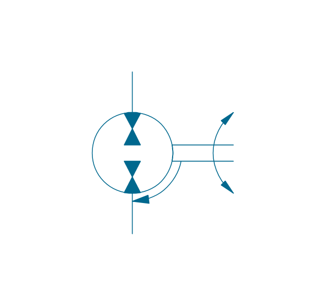
Pump-motor, fixed, external drain
Pump-motor, fixed, external drain
Pump-motor, variable
Pump-motor, variable, external drain
Pump-motor, var., manual override
Pump-motor, var., manual override, drain
Pump-motor, var., solenoid

Pump-motor, var., solenoid, drain

Pump-motor, var., solenoid 2
Pump-motor, var., solenoid 2, drain
Pump-motor, var., var. solenoid
Pump-motor, var., var. solenoid, drain

Pump-motor, var., var. solenoid 2

Pump-motor, var., var. solenoid 2, drain
Pump-motor, var., var., roller
Pump-motor, var., roller, drain
Pump, fixed 2
Pump, fixed 2, drain
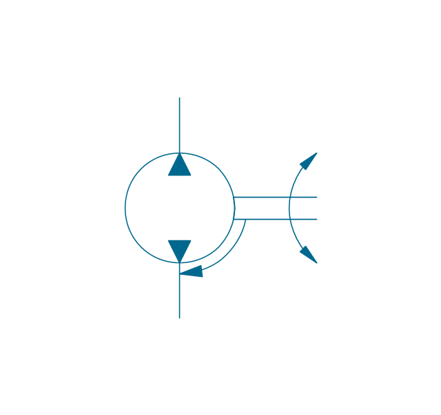
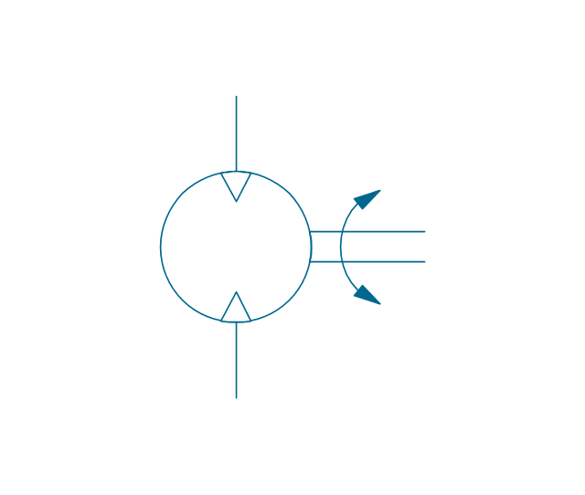
Pump, variable (sgl side)
-hydraulic-pumps-and-motors---vector-stencils-library.png--diagram-flowchart-example.png)
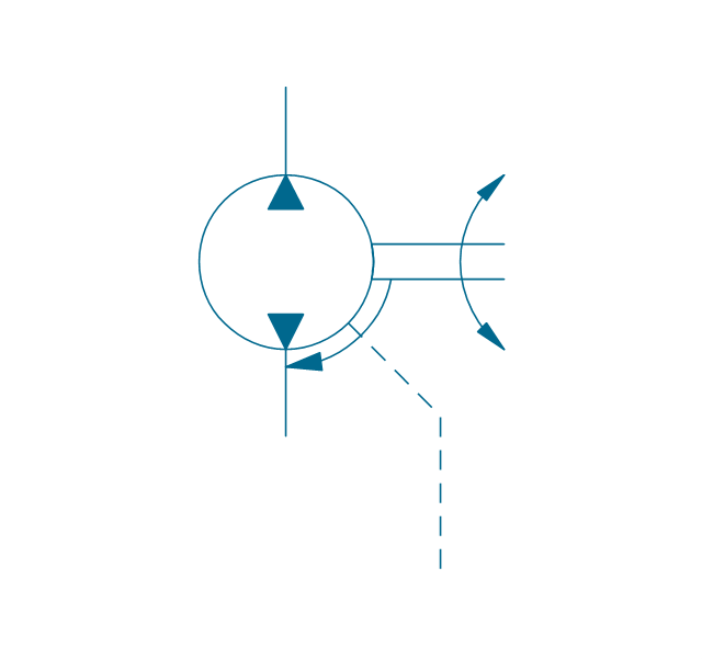
Pump, variable (sgl side), drain
,-drain-hydraulic-pumps-and-motors---vector-stencils-library.png--diagram-flowchart-example.png)
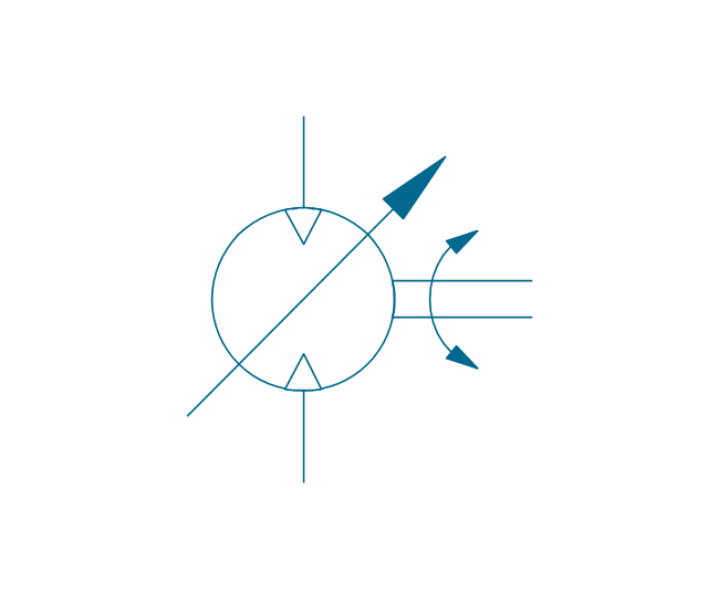
Pump, variable (dbl side)
-hydraulic-pumps-and-motors---vector-stencils-library.png--diagram-flowchart-example.png)
Pump, variable (dbl side), drain
,-drain-hydraulic-pumps-and-motors---vector-stencils-library.png--diagram-flowchart-example.png)
Motor, fixed 2
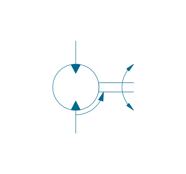
Motor, variable (sgl side)
-hydraulic-pumps-and-motors---vector-stencils-library.png--diagram-flowchart-example.png)
Motor, variable (dbl side)
-hydraulic-pumps-and-motors---vector-stencils-library.png--diagram-flowchart-example.png)
Motor, fixed 2, drain
Motor, variable (sgl side), drain
,-drain-hydraulic-pumps-and-motors---vector-stencils-library.png--diagram-flowchart-example.png)
Motor, variable (dbl side), drain
,-drain-hydraulic-pumps-and-motors---vector-stencils-library.png--diagram-flowchart-example.png)
Pump-motor, fixed 2
Pump-motor, fixed 2, drain
Pump-motor, variable (sgl side)
-hydraulic-pumps-and-motors---vector-stencils-library.png--diagram-flowchart-example.png)
Pump-motor, variable (sgl side), drain
,-drain-hydraulic-pumps-and-motors---vector-stencils-library.png--diagram-flowchart-example.png)
Pump-motor, variable (dbl side)
-hydraulic-pumps-and-motors---vector-stencils-library.png--diagram-flowchart-example.png)
Pump-motor, variable (dbl side), drain
,-drain-hydraulic-pumps-and-motors---vector-stencils-library.png--diagram-flowchart-example.png)
Pump, variable displacement
Motor, variable displacement
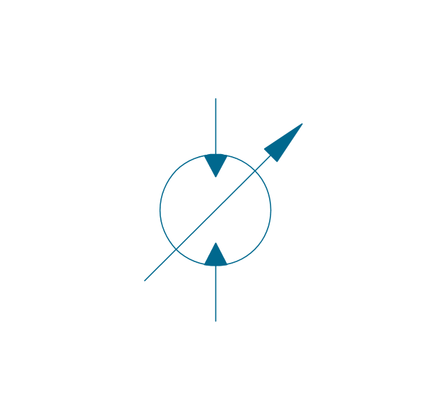
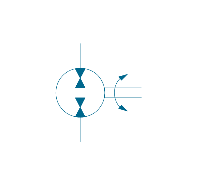
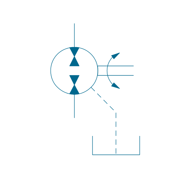
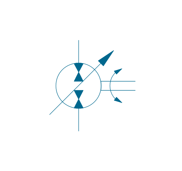
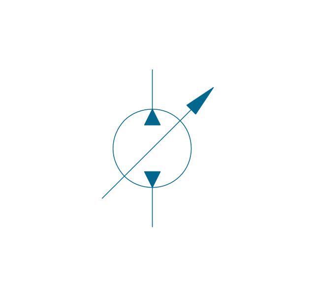
Pump-motor, variable displacement
Floating motor
Pressure compensator
The vector stencils library "Pneumatic pumps and motors" contains 39 symbols of pneumatic pumps, motors and pump-motors.
Use these shapes for designing the engineering drawings of pneumatic circuits in the ConceptDraw PRO diagramming and vector drawing software extended with the Mechanical Engineering solution from the Engineering area of ConceptDraw Solution Park.
www.conceptdraw.com/ solution-park/ engineering-mechanical
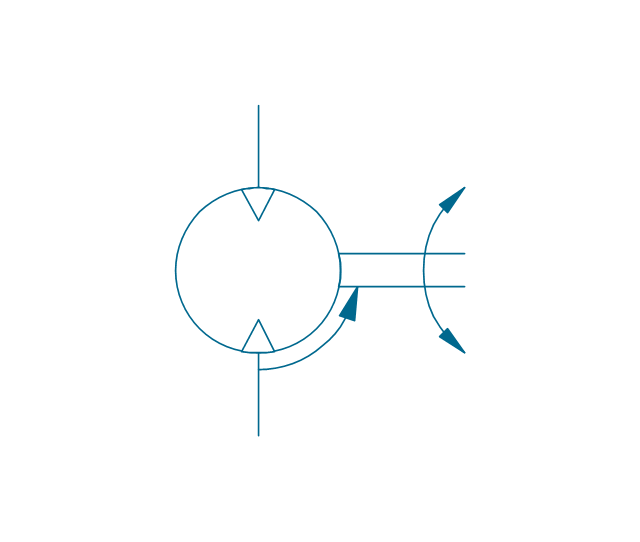
Pump, pneumatic
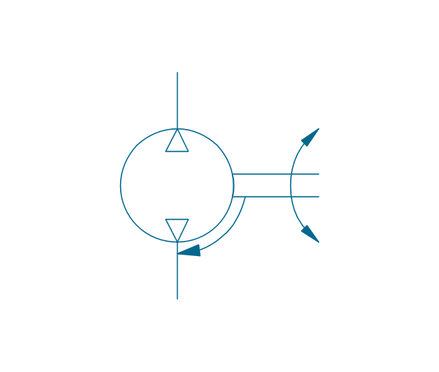
Motor, pneumatic
Pump-motor, pneumatic
Pump, fixed, external drain
Pump, variable
Pump, var., manual override
Pump, var., solenoid
Pump, var., solenoid 2

Pump, var., var. solenoid

Pump, var., var. solenoid 2

Pump, var., var., roller
Motor, fixed, external drain
Motor, variable
Motor, var., manual override

Motor, var., solenoid

Motor, var., solenoid 2
Motor, var., var. solenoid

Motor, var., var. solenoid 2
Motor, var., var., roller

Pump-motor, fixed, external drain
Pump-motor, variable

Pump-motor, var., manual override
Pump-motor, var., solenoid
Pump-motor, var., solenoid 2
Pump-motor, var., var. solenoid
Pump-motor, var., var. solenoid 2

Pump-motor, var., var., roller
Pump, variable (sgl side)
-pneumatic-pumps-and-motors---vector-stencils-library.png--diagram-flowchart-example.png)
Pump, variable (dbl side)
-pneumatic-pumps-and-motors---vector-stencils-library.png--diagram-flowchart-example.png)
Pump, fixed 2
Motor, fixed 2
Motor, variable (sgl side)
-pneumatic-pumps-and-motors---vector-stencils-library.png--diagram-flowchart-example.png)
Motor, variable (dbl side)
-pneumatic-pumps-and-motors---vector-stencils-library.png--diagram-flowchart-example.png)
Pump-motor, fixed 2
Pump-motor, variable (sgl side)
-pneumatic-pumps-and-motors---vector-stencils-library.png--diagram-flowchart-example.png)
Pump-motor, variable (dbl side)
-pneumatic-pumps-and-motors---vector-stencils-library.png--diagram-flowchart-example.png)
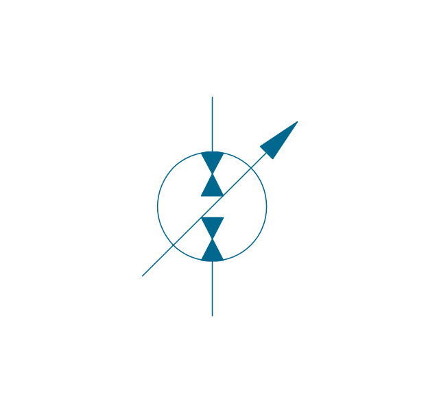
Pump, variable displacement
Motor, variable displacement
Pump-motor, variable displacement
Interior Design. Piping Plan — Design Elements

The vector stencils library "Valves" contains 91 symbols of piping and plumbing valves.
"A valve is a device that regulates, directs or controls the flow of a fluid (gases, liquids, fluidized solids, or slurries) by opening, closing, or partially obstructing various passageways. Valves are technically valves fittings, but are usually discussed as a separate category. In an open valve, fluid flows in a direction from higher pressure to lower pressure.
The simplest, and very ancient, valve is simply a freely hinged flap which drops to obstruct fluid (gas or liquid) flow in one direction, but is pushed open by flow in the opposite direction. This is called a check valve, as it prevents or "checks" the flow in one direction.
People in developed nations use valves in their daily lives, including plumbing valves, such as taps for tap water, gas control valves on cookers, small valves fitted to washing machines and dishwashers, safety devices fitted to hot water systems..." [Valve. Wikipedia]
Use the design elements library "Valves" to draw building plans, schematic diagrams, blueprints, or technical drawings of industrial piping systems; process, vacuum, and fluids piping; hydraulics piping; air and gas piping; materials distribution; and liquid transfer systems using the ConceptDraw PRO diagramming and vector drawing software.
The shapes library "Valves" is included in the Plumbing and Piping Plans solution from the Building Plans area of ConceptDraw Solution Park.
Valve symbols

The vector stencils library "Valve assembly" contains 141 symbols of pressure and flow regulators, flow direction indicators, controls, and symbols to design flow paths of control valves.
Use these valve assembly shapes to design the engineering drawings of hydraulic and pneumatic valve assemblies in fluid power systems.
"Control valves are valves used to control conditions such as flow, pressure, temperature, and liquid level by fully or partially opening or closing in response to signals received from controllers that compare a "setpoint" to a "process variable" whose value is provided by sensors that monitor changes in such conditions.
The opening or closing of control valves is usually done automatically by electrical, hydraulic or pneumatic actuators. Positioners are used to control the opening or closing of the actuator based on electric, or pneumatic signals.
A control valve consists of three main parts in which each part exist in several types and designs: Valve's actuator, Valve's positioner, Valve's body.
" [Control valves. Wikipedia]
The shapes example "" was created using the ConceptDraw PRO diagramming and vector drawing software extended with the Mechanical Engineering solution from the Engineering area of ConceptDraw Solution Park.
Valve assembly symbols
 Mechanical Engineering
This solution extends ConceptDraw DIAGRAM.9 mechanical drawing software (or later) with samples of mechanical drawing symbols, templates and libraries of design elements, for help when drafting mechanical engineering drawings, or parts, assembly, pneumatic,
The vector stencils library "Valves" contains 91 symbols of valves. Use it for drawing plumbing and piping plans, schematic diagrams and blueprints of industrial piping systems; process, vacuum, and fluids piping; hydraulics piping; air and gas piping; materials distribution; and liquid transfer systems in the ConceptDraw PRO diagramming and vector drawing software extended with the Plumbing and Piping Plans solution from the Building Plans area of ConceptDraw Solution Park.
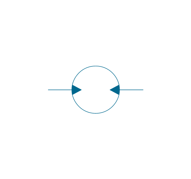
In-line valve

3-way valve

4-way valve

Screw-down valve

Lock-shield valve

Reel valve

Relief valve

Relief valve 2

Relief valve 3

Relief valve 4

Angle valve

Angle valve 2

Angle valve 3

Angle valve 4

Check valve

Check valve 2

Screwdown valve

Float operated valve

Float operated valve 2

Flanged valve

Flanged valve 2

Butterfly valve

Butterfly valve 2

Globe valve

Globe valve 2

Globe valve 3

Needle valve

Needle valve 2

Needle valve 3

Needle valve 4

Diaphragm valve

Diaphragm valve 2

Diaphragm valve 3

Wedge gate valve

Parallel side valve

Gate valve

Ball valve

Ball valve 2

Ball valve 3

Powered control valve

Powered control valve 2

Powered control valve 3

Relief angle valve, pressure

Relief angle valve, vacuum

Reducing valve

Reducing valve 2

Plug valve

Plug valve 2

Plug valve, straight through

3-way plug valve

Plug valve, T-port

Plug valve, L-port

3-way plug valve

3-way plug valve 2

3-way plug valve 3

3-way plug valve, T-port

3-way plug valve, L-port

Mixing valve

Characterized port valve

Manual isolation

Power signal

Statically loaded

Spring loaded

Spring loaded 2

Remote control

Diaphragm

Diaphragm, positioner

Chain operated

Gear operated

Solenoid

Weight loaded

Weight loaded 2

Weight loaded 3

Float operated

Float operated 2

Dash-pot

Dash-pot 2

Piston

Quick opening

Quick opening 2

Quick closing

Quick closing 2

Connecting unit

Connecting unit 2

Connecting unit 3

Motor element

Motor element, opens on failure

Motor element, closes on failure

Motor element, retains position on fail

Motor element, safe direction

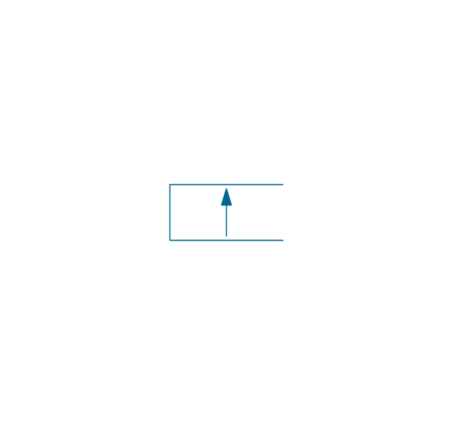
Regulating

The vector stencils library "Valves" contains 91 symbols of piping and plumbing valves.
"A valve is a device that regulates, directs or controls the flow of a fluid (gases, liquids, fluidized solids, or slurries) by opening, closing, or partially obstructing various passageways. Valves are technically valves fittings, but are usually discussed as a separate category. In an open valve, fluid flows in a direction from higher pressure to lower pressure.
The simplest, and very ancient, valve is simply a freely hinged flap which drops to obstruct fluid (gas or liquid) flow in one direction, but is pushed open by flow in the opposite direction. This is called a check valve, as it prevents or "checks" the flow in one direction.
People in developed nations use valves in their daily lives, including plumbing valves, such as taps for tap water, gas control valves on cookers, small valves fitted to washing machines and dishwashers, safety devices fitted to hot water systems..." [Valve. Wikipedia]
Use the design elements library "Valves" to draw building plans, schematic diagrams, blueprints, or technical drawings of industrial piping systems; process, vacuum, and fluids piping; hydraulics piping; air and gas piping; materials distribution; and liquid transfer systems using the ConceptDraw PRO diagramming and vector drawing software.
The shapes library "Valves" is included in the Plumbing and Piping Plans solution from the Building Plans area of ConceptDraw Solution Park.
"A valve is a device that regulates, directs or controls the flow of a fluid (gases, liquids, fluidized solids, or slurries) by opening, closing, or partially obstructing various passageways. Valves are technically valves fittings, but are usually discussed as a separate category. In an open valve, fluid flows in a direction from higher pressure to lower pressure.
The simplest, and very ancient, valve is simply a freely hinged flap which drops to obstruct fluid (gas or liquid) flow in one direction, but is pushed open by flow in the opposite direction. This is called a check valve, as it prevents or "checks" the flow in one direction.
People in developed nations use valves in their daily lives, including plumbing valves, such as taps for tap water, gas control valves on cookers, small valves fitted to washing machines and dishwashers, safety devices fitted to hot water systems..." [Valve. Wikipedia]
Use the design elements library "Valves" to draw building plans, schematic diagrams, blueprints, or technical drawings of industrial piping systems; process, vacuum, and fluids piping; hydraulics piping; air and gas piping; materials distribution; and liquid transfer systems using the ConceptDraw PRO diagramming and vector drawing software.
The shapes library "Valves" is included in the Plumbing and Piping Plans solution from the Building Plans area of ConceptDraw Solution Park.
Valve symbols
- Directional control valve | Double Acting Solenoid Valve Symbol
- Solenoid Valve Symbols Meaning
- Plumbing Solenoid Valve Symbols
- Electrical Symbols — Electrical Circuits | Chemical and Process ...
- Electrical Symbols , Electrical Diagram Symbols | Design elements ...
- Mechanical Drawing Symbols | Technical Drawing Software ...
- Hydraulic 4-ported 3-position valve template - Win | Solenoid ...
- Process Flow Diagram Symbols | Water Spigot Cad Symbol
- Hydraulic Symbol Stencil
- Solenoid And Pneumatic Cylinder Electrical Symbol List Pdf