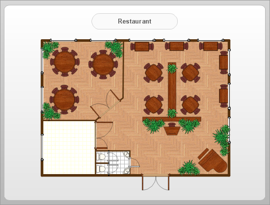
How To Create Restaurant Floor Plan in Minutes

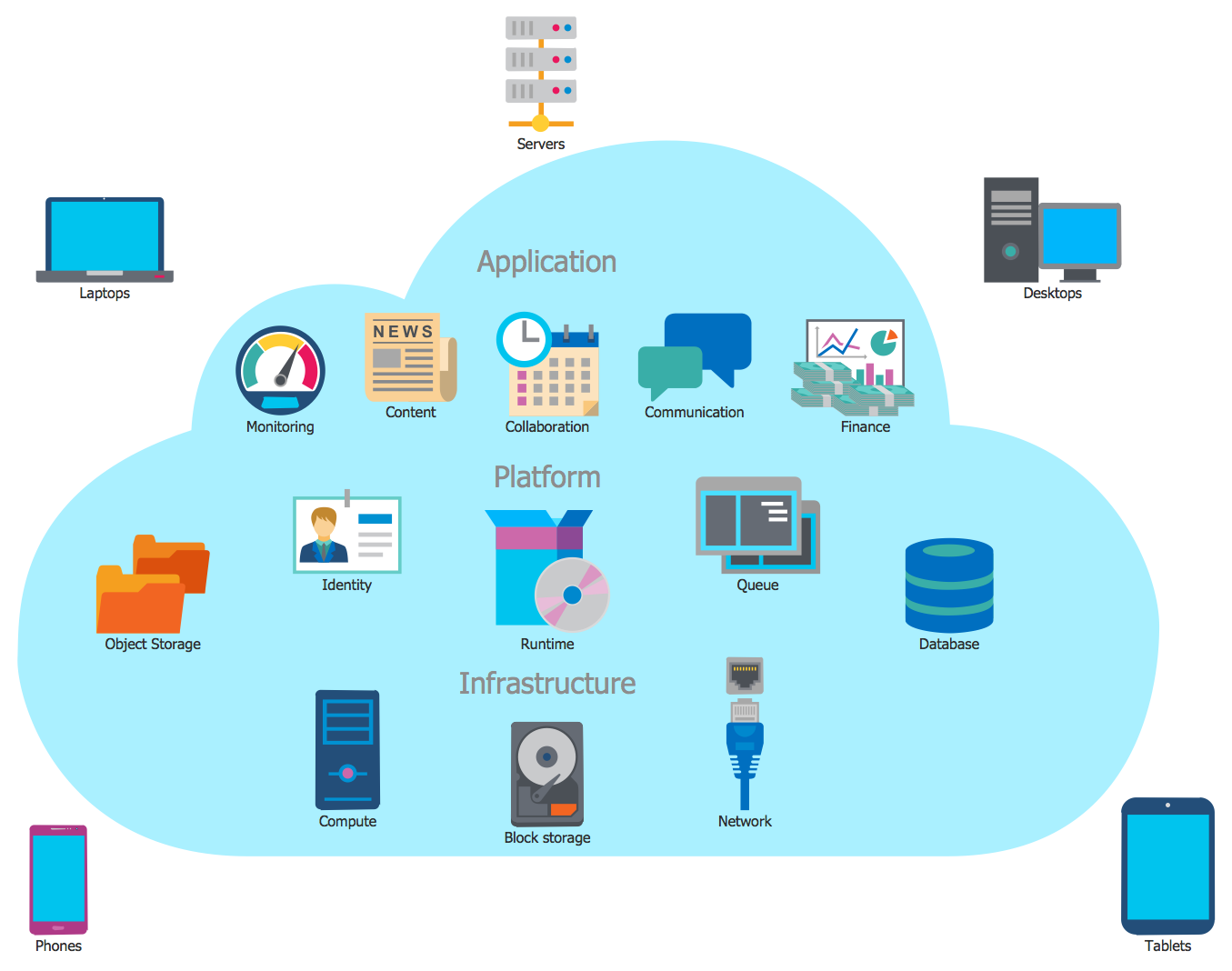
Cloud Computing Architecture
The vector stencils library "AWS Developer Tools and Contact Center" contains 7 Amazon Web Services developer tools and contact center icons: AWS CodeStar, AWS CodeBuild, AWS CodeCommit, AWS CodeDeploy, AWS CodePipeline, AWS X-Ray, Amazon Connect.
Use it to draw AWS architecture diagrams with ConceptDraw PRO software.
Amazon Developer Tools services includes: "AWS CodeCommit (Store Code in Private Git Repositories), AWS CodeBuild (Build and Test Code), AWS CodeDeploy (Automate Code Deployment), AWS CodePipeline (Release Software using Continuous Delivery), AWS X-Ray (Analyze and Debug Your Applications), AWS Command Line Interface (Unified Tool to Manage AWS Services)" [aws.amazon.com]
The AWS icons example "Design elements - AWS Developer Tools" is included in the AWS Architecture Diagrams solution from the Computer and Networks area of ConceptDraw Solution Park.
Amazon Web Services icons
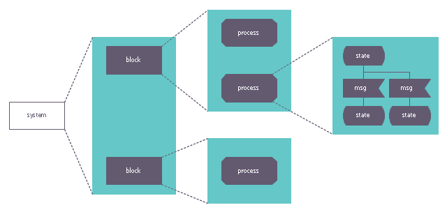
This system architecture diagram example was redesigned from the Wikimedia Commons file: SdlArchitecture.JPG. [commons.wikimedia.org/ wiki/ File:SdlArchitecture.JPG]
This file is licensed under the Creative Commons Attribution-Share Alike 3.0 Unported license. [creativecommons.org/ licenses/ by-sa/ 3.0/ deed.en]
"Architecture.
An SDL system is made of functional blocks and each block can be further decomposed in sub-blocks. The lowest level block is composed of one or several process described as finite state machines." [Specification and Description Language. Wikipedia]
The diagram example "SDL Architecture" was created using the ConceptDraw PRO diagramming and vector drawing software extended with the Specification and Description Language (SDL) solution from the Engineering area of ConceptDraw Solution Park.
System architecture
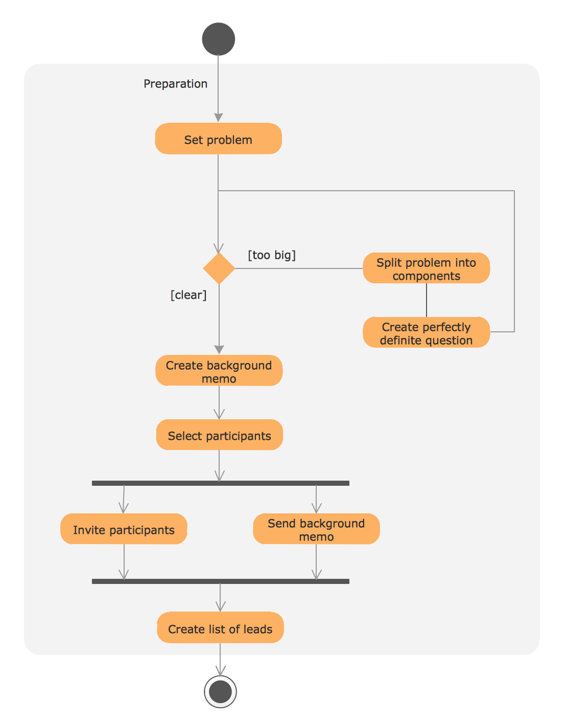
UML Process Diagram Example
Amazon Cloud Computing Architecture

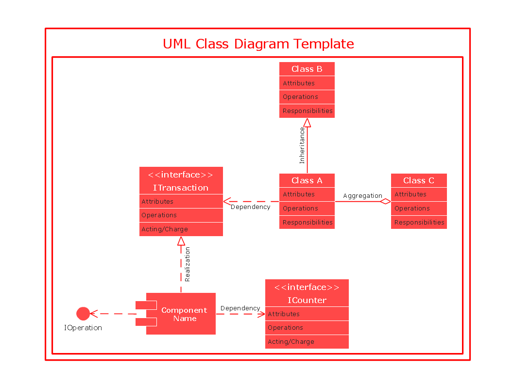
UML Class Diagrams. Diagramming Software for Design UML Diagrams


UML Class Diagram
 Azure Architecture
Azure Architecture solution bundles into one handy tool everything you need to create effective Azure Architecture diagrams. It adds the extra value to versatile ConceptDraw DIAGRAM software and extends the users capabilities with comprehensive collection of Microsoft Azure themed graphics, logos, preset templates, wide array of predesigned vector symbols that covers the subjects such as Azure management, Azure storage, and Azure services, amongst others, and allow you to illustrate Azure Architecture diagrams at any degree of complexity, to present visually your Azure cloud system architecture with professional style, to design Azure cloud topology, to document Windows Azure Architecture and Azure Cloud System Architecture, to visualize the great abilities and work of Microsoft Azure Cloud System and Azure services.
 Computer and Networks Area
The solutions from Computer and Networks Area of ConceptDraw Solution Park collect samples, templates and vector stencils libraries for drawing computer and network diagrams, schemes and technical drawings.
- Design elements - AWS Developer Tools | AWS Architecture ...
- Vector Code Maintenance Icon
- Scheduler agent supervisor pattern | Valet key pattern | Health ...
- Software and Database Design with ConceptDraw DIAGRAM | Data ...
- Atm Architecture Diagram
- Venn Diagram Codes Programming Visual Basic
- Specification and Description Language (SDL) | SDL Architecture ...
- Atm Software Architecture Diagram
- Diagramming Software for Design UML Use Case Diagrams | UML ...
- Bank UML Diagram | AWS Architecture Diagrams | UML for Bank ...