This reflected ceiling plan sample was created on the base of the article "How to Read a Reflected Ceiling Plan" from wikiHow.com.
"A reflected ceiling plan (RCP) is a drawing, which shows the items that are located on the ceiling of a room or space. It is referred to as a reflected ceiling plan since it is drawn to display a view of the ceiling as if it was reflected onto a mirror on the floor. This way the reflected ceiling plan has the same orientation as the floor plan associated with it. It is as if the ceiling was see-through and you could see right through it to the floor below. Architects and interior designers draw reflected ceiling plans when designing spaces." [wikihow.com/ Read-a-Reflected-Ceiling-Plan]
The HVAC layout example "RCP- HVAC layout" was created using the ConceptDraw PRO diagramming and vector drawing software extended with the Reflected Ceiling Plans solution from the Building Plans area of ConceptDraw Solution Park.
Reflected ceiling plan

This HVAC floor plan sample shows the ventilation duct system layout.
"Ducts are used in heating, ventilation, and air conditioning (HVAC) to deliver and remove air. The needed airflows include, for example, supply air, return air, and exhaust air. Ducts commonly also deliver ventilation air as part of the supply air. As such, air ducts are one method of ensuring acceptable indoor air quality as well as thermal comfort.
A duct system is also called ductwork. Planning (laying out), sizing, optimizing, detailing, and finding the pressure losses through a duct system is called duct design." [Duct (flow). Wikipedia]
The HVAC floor plan example "Ductwork layout" was created using the ConceptDraw PRO diagramming and vector drawing software extended with the HVAC Plans solution from the Building Plans area of ConceptDraw Solution Park.
HVAC floor plan

 HVAC Plans
Use HVAC Plans solution to create professional, clear and vivid HVAC-systems design plans, which represent effectively your HVAC marketing plan ideas, develop plans for modern ventilation units, central air heaters, to display the refrigeration systems for automated buildings control, environmental control, and energy systems.
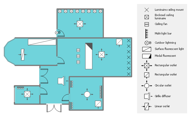
This reflected ceiling plan (RCP) sample shows lighting and HVAC layout.
"A "reflected ceiling plan" shows a view of the room as if looking from above, through the ceiling, at a mirror installed one foot below the ceiling level, which shows the reflected image of the ceiling above. This convention maintains the same orientation of the floor and ceilings plans - looking down from above. Reflected Ceiling Plans or RCP's are used by designers and architects to demonstrate lighting, visible mechanical features, and ceiling forms as part of the documents provided for construction." [Floor plan. Wikipedia]
The lighting and HVAC layout example "Reflected ceiling plan" was created using the ConceptDraw PRO diagramming and vector drawing software extended with the Reflected Ceiling Plans solution from the Building Plans area of ConceptDraw Solution Park.
Lighting and HVAC layout
 Network Layout Floor Plans
Network Layout Floor Plans solution extends ConceptDraw PRO software functionality with powerful tools for quick and efficient documentation the network equipment and displaying its location on the professionally designed Network Layout Floor Plans. Never before creation of Network Layout Floor Plans, Network Communication Plans, Network Topologies Plans and Network Topology Maps was not so easy, convenient and fast as with predesigned templates, samples, examples and comprehensive set of vector design elements included to the Network Layout Floor Plans solution. All listed types of plans will be a good support for the future correct cabling and installation of network equipment.
 Plant Layout Plans
This solution extends ConceptDraw PRO v.9.5 plant layout software (or later) with process plant layout and piping design samples, templates and libraries of vector stencils for drawing Plant Layout plans. Use it to develop plant layouts, power plant desig
This HVAC plan sample shows the air handler layout on the floor plan.
"An air handler, or air handling unit (often abbreviated to AHU), is a device used to condition and circulate air as part of a heating, ventilating, and air-conditioning (HVAC) system. An air handler is usually a large metal box containing a blower, heating or cooling elements, filter racks or chambers, sound attenuators, and dampers. Air handlers usually connect to a ductwork ventilation system that distributes the conditioned air through the building and returns it to the AHU. Sometimes AHUs discharge (supply) and admit (return) air directly to and from the space served without ductwork.
Small air handlers, for local use, are called terminal units, and may only include an air filter, coil, and blower; these simple terminal units are called blower coils or fan coil units. A larger air handler that conditions 100% outside air, and no recirculated air, is known as a makeup air unit (MAU). An air handler designed for outdoor use, typically on roofs, is known as a packaged unit (PU) or rooftop unit (RTU)." [Air handler. Wikipedia]
The floor plan example "Air handler - HVAC plan" was created using the ConceptDraw PRO diagramming and vector drawing software extended with the HVAC Plans solution from the Building Plans area of ConceptDraw Solution Park.
Floor plan

Create Block Diagram

- HVAC Plans
- HVAC Plans | How to Create a HVAC Plan | RCP - HVAC layout | Hvac
- HVAC Plans | RCP - HVAC layout | How to Create a HVAC Plan ...
- Hvac Duct Design Example
- Ductwork layout | HVAC Business Plan | HVAC Plans | Air Duct ...
- Hvac Equipment Layout
- HVAC Plans | Ductwork layout | Ventilation system layout | Sample ...
- Ductwork layout | HVAC Plans | HVAC Business Plan | Sample Hvac ...
- Hvac Layout Of Office
- Network Layout Floor Plans | How To Draw Building Plans | HVAC ...
- RCP - HVAC layout | Reflected ceiling plan | Design elements ...
- Reflected ceiling plan | RCP - HVAC layout | How to Create a ...
- HVAC Business Plan | HVAC Plans | HVAC Marketing Plan | Sample ...
- Hvac Plant Layout Diagram
- Sample Layout Of Air Filters In Hvac Plan
- Reflected ceiling plan | RCP - HVAC layout | Reflected Ceiling Plans ...
- Air handler- HVAC plan | Ventilation system layout | HVAC control ...
- Ventilation system layout | Ventilation duct system | Sample Of Bacteria
- Restaurant Floor Plan | HVAC Business Plan | Restaurant Layouts ...
- Ductwork layout | Ventilation system layout | RCP - HVAC layout ...