Process Flow Diagram Symbols

Electrical Symbols — Inductors

Electrical Symbols, Electrical Diagram Symbols

Electrical Symbols — Transformers and Windings
 Chemical and Process Engineering
This chemical engineering solution extends ConceptDraw DIAGRAM.9.5 (or later) with process flow diagram symbols, samples, process diagrams templates and libraries of design elements for creating process and instrumentation diagrams, block flow diagrams (BFD
The vector stencils library "Inductors" contains 41 symbols of inductor elements for drawing electronic circuit diagrams.
"An inductor, also called a coil or reactor, is a passive two-terminal electrical component which resists changes in electric current passing through it. It consists of a conductor such as a wire, usually wound into a coil. When a current flows through it, energy is stored temporarily in a magnetic field in the coil. When the current flowing through an inductor changes, the time-varying magnetic field induces a voltage in the conductor, according to Faraday’s law of electromagnetic induction, which opposes the change in current that created it.
An inductor is characterized by its inductance, the ratio of the voltage to the rate of change of current, which has units of henries (H). Inductors have values that typically range from 1 µH (10-6H) to 1 H. Many inductors have a magnetic core made of iron or ferrite inside the coil, which serves to increase the magnetic field and thus the inductance. Along with capacitors and resistors, inductors are one of the three passive linear circuit elements that make up electric circuits. Inductors are widely used in alternating current (AC) electronic equipment, particularly in radio equipment. They are used to block the flow of AC current while allowing DC to pass; inductors designed for this purpose are called chokes. They are also used in electronic filters to separate signals of different frequencies, and in combination with capacitors to make tuned circuits, used to tune radio and TV receivers." [Inductor. Wikipedia]
The symbols example "Design elements - Inductors" was drawn using the ConceptDraw PRO diagramming and vector drawing software extended with the Electrical Engineering solution from the Engineering area of ConceptDraw Solution Park.
Inductor elements

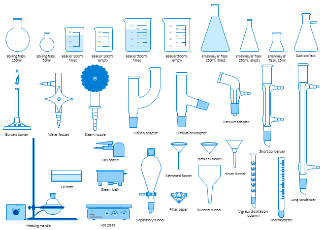
The vector stencils library "Laboratory equipment" contains 31 clipart icons of chemical laboratory equipment and labware for drawing part assembly and mounting schemes of glassware apparatus in chemical experiment diagrams and illustrations.
"Laboratory glassware refers to a variety of equipment, traditionally made of glass, used for scientific experiments and other work in science, especially in chemistry and biology laboratories. ...
Glass use in laboratory applications is not as commonplace as it once was because of cheaper, less breakable, plasticware; however, certain applications still require glassware because glass is relatively inert, transparent, heat-resistant, and easy to customize. The type of glass used is dependent on the application. Borosilicate glass, which is commonly used in reagent bottles, can withstand thermal stress. Quartz glass, which is common in cuvettes, can withstand high temperatures and is transparent in certain parts of the electromagnetic spectrum. Darkened brown or amber (actinic) glass, which is common in dark storage bottles, can block ultraviolet and infrared radiation. Heavy-wall glass, which is common in glass pressure reactors, can withstand pressurized applications." [Laboratory glassware. Wikipedia]
The chemical symbols example "Design elements - Laboratory equipment" was created using the ConceptDraw PRO software extended with the Chemistry solution from the Science and Education area of ConceptDraw Solution Park.
Labware
The vector stencils library "Transformers and windings" contains 29 element symbols of transformers, windings, couplers, metering devices, transductors, magnetic cores, chokes, and a variometer.
Use it to design the electromechanical device schematics and electronic circuit diagrams in the ConceptDraw PRO diagramming and vector drawing software extended with the Electrical Engineering solution from the Engineering area of ConceptDraw Solution Park.
www.conceptdraw.com/ solution-park/ engineering-electrical
Coaxial choke

Transductor

Saturating transformer

1-phase induction voltage regulator

Triplex induction voltage regulator

Induction voltage regulator

Current transformer 2

Current transformer 3

Potential transformer 2

Potential transformer with 3 windings

Outdoor metering device

Linear coupler

Magnetic core, 1 line

Magnetic core, 2 lines

Choke

Variometer

Air-core transformer

Magnetic-core transformer

Air-core transformer, 1 winding adjustable

Magnetic-core transformer, 1 winding adjustable

Air-core transformer, 2 windings adjustable

Magnetic-core transformer, 2 windings adjustable

Air-core transformer, mutual inductor

Magnetic-core transformer, mutual inductor

Transformer 2

Adjustable transformer, 1 winding

Adjustable transformer, mutual inductor

Current transformer 1

Potential transformer

- Reactor Symbol In Electrical
- Process Flow Diagram Symbols | Reactor Symbol In Refinery Process
- Symbol Of Electrical Reactor Transformer
- Engineering Symbol Of Reactor
- Reactor Transformer Symbol
- Electrical Symbols , Electrical Diagram Symbols | Electrical Symbols ...
- Chemical Engineering Drawing Reactors Symbol N Uses
- Electrical Symbols — Transformers and Windings | Electrical ...
- Electrical Symbols — Transformers and Windings | Electrical ...
- Electrical Symbols — Transformers and Windings | Electrical ...
- Electrical Symbols — Power Sources | Electrical Symbols , Electrical ...
- Process Flow Diagram Symbols | Chemical and Process ...
- Electrical Symbols — Transformers and Windings | Electrical ...
- Electrical Symbols — Inductors | Electrical Symbols — Transformers ...
- Design elements - Inductors | Design elements - Transformers and ...
- Electrical Symbols — Inductors | Electrical Symbols , Electrical ...
- Design elements - Inductors | Electrical Symbols — Inductors ...
- Electrical Symbols , Electrical Diagram Symbols | Electrical Drawing ...
- How to Draw a Chemical Process Flow Diagram
- Electrical Symbols — Transformers and Windings | Electrical ...