Entity Relationship Diagram Examples


 Active Directory Diagrams
Active Directory Diagrams solution significantly extends the capabilities of ConceptDraw DIAGRAM software with special Active Directory samples, convenient template and libraries of Active Directory vector stencils, common icons of sites and services, icons of LDPA elements, which were developed to help you in planning and modelling network structures and network topologies, in designing excellently looking Active Directory diagrams, Active Directory Structure diagrams, and Active Directory Services diagram, which are perfect way to visualize detailed structures of Microsoft Windows networks, Active Directory Domain topology, Active Directory Site topology, Organizational Units (OU), and Exchange Server organization.
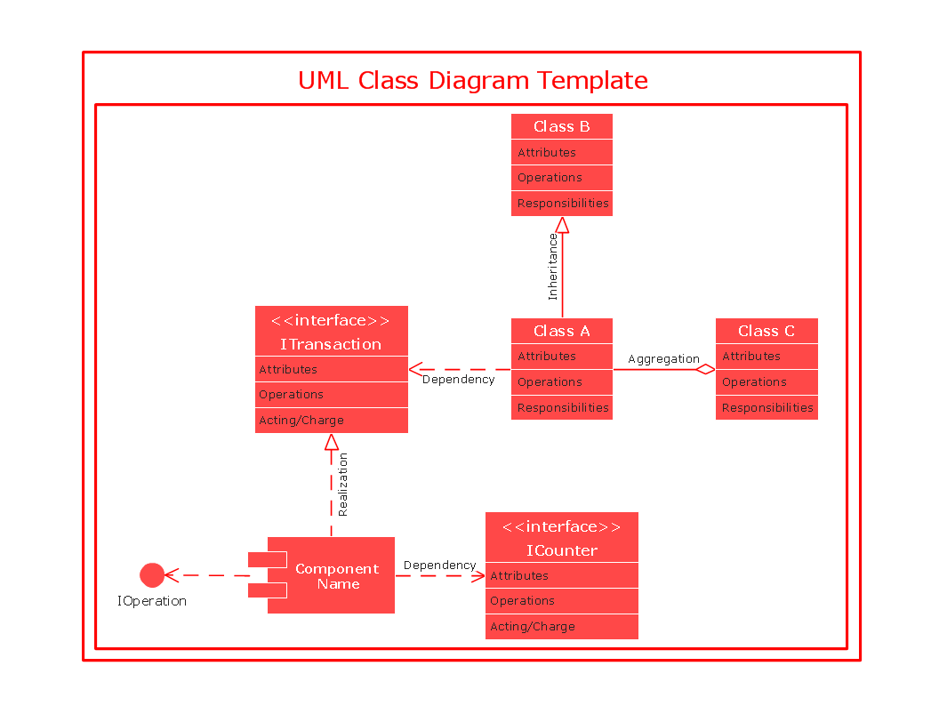
UML Class Diagram

 AWS Architecture Diagrams
AWS Architecture Diagrams with powerful drawing tools and numerous predesigned Amazon icons and AWS simple icons is the best for creation the AWS Architecture Diagrams, describing the use of Amazon Web Services or Amazon Cloud Services, their application for development and implementation the systems running on the AWS infrastructure. The multifarious samples give you the good understanding of AWS platform, its structure, services, resources and features, wide opportunities, advantages and benefits from their use; solution’s templates are essential and helpful when designing, description and implementing the AWS infrastructure-based systems. Use them in technical documentation, advertising and marketing materials, in specifications, presentation slides, whitepapers, datasheets, posters, etc.
Entity-Relationship Diagram

Active Directory
Entity Relationship Software

Network Diagramming Software for Design Network Layout Diagrams
_Win_Mac.png)

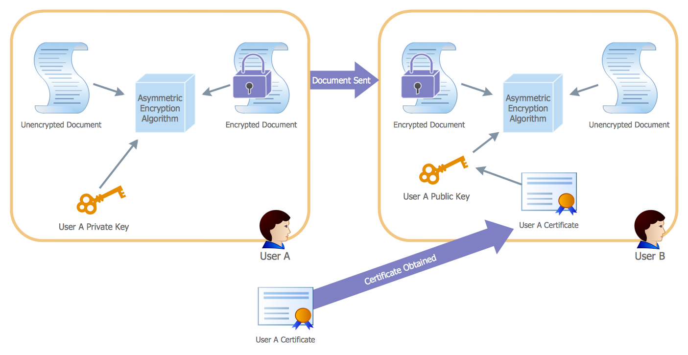
- Professional Certificate Maker
- Entity Relationship Diagram Examples | UML Class Diagram ...
- Wide area network (WAN) topology. Computer and Network ...
- Modern Training Certificates Templates
- Active Directory - Vector stencils library | Active Directory Sites and ...
- EFS Operation | Active Directory Diagrams | ConceptDraw Arrows10 ...
- Organizational Structure Total Quality Management | Examples of ...
- Active Directory Domain Services diagram
- CS Odessa Improves ConceptDraw AWS Solution
- Download and Install ConceptDraw Office on your PC | Download ...