Interior Design. Registers, Drills and Diffusers — Design Elements

How To use House Electrical Plan Software


Electrical Symbols, Electrical Diagram Symbols

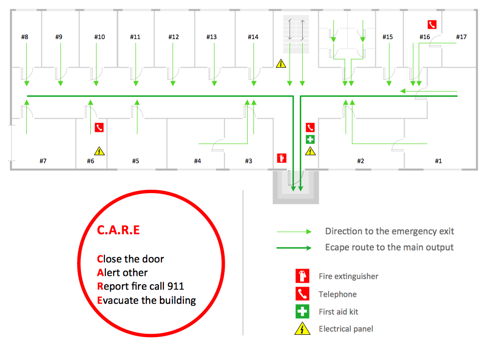
Fire Exit Plan
 HVAC Plans
Use HVAC Plans solution to create professional, clear and vivid HVAC-systems design plans, which represent effectively your HVAC marketing plan ideas, develop plans for modern ventilation units, central air heaters, to display the refrigeration systems for automated buildings control, environmental control, and energy systems.
 Network Layout Floor Plans
Network Layout Floor Plans solution extends ConceptDraw DIAGRAM software functionality with powerful tools for quick and efficient documentation the network equipment and displaying its location on the professionally designed Network Layout Floor Plans. Never before creation of Network Layout Floor Plans, Network Communication Plans, Network Topologies Plans and Network Topology Maps was not so easy, convenient and fast as with predesigned templates, samples, examples and comprehensive set of vector design elements included to the Network Layout Floor Plans solution. All listed types of plans will be a good support for the future correct cabling and installation of network equipment.
How to Draw a Building Plans
This electrical floot plan sample shows the Power socket outlet layout.
"The term plug is in general and technical use in all forms of English, common alternatives being power plug, electric plug, and (in the UK) plug top. The normal technical term (in both British and International English) for an AC power socket is socket-outlet, but in non-technical common use a number of other terms are used. In British English the general term is socket, but there are numerous common alternatives, including power point, plug socket, wall socket, and wall plug. In American English receptacle and outlet are common, sometimes with qualifiers such as wall outlet, electrical outlet and electrical receptacle, all of these sometimes to be found in the same document. A socket may be surrounded by a decorative and/ or protective cover called a wall plate, face plate, outlet cover, socket cover, or wall cover. In some designs this is an integral piece with the socket itself, bought and installed as a single unit." [AC power plugs and sockets. Wikipedia]
The electrical floot plan example "Power socket outlet layout" was created using the ConceptDraw PRO diagramming and vector drawing software extended with the Electric and Telecom Plans solution from the Building plans area of ConceptDraw Solution Park.
Electrical floot plan

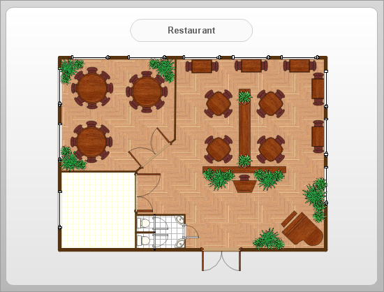
This cafe electrical floor plan sample shows the outlet and switch layout.
"An electrical drawing, is a type of technical drawing that shows information about power, lighting, and communication for an engineering or architectural project. Any electrical working drawing consists of "lines, symbols, dimensions, and notations to accurately convey an engineering's design to the workers, who install the electrical system on the job".
A complete set of working drawings for the average electrical system in large projects usually consists of:
(1) A plot plan showing the building's location and outside electrical wiring.
(2) Floor plans showing the location of electrical systems on every floor.
(3) Power-riser diagrams showing panel boards.
(4) Control wiring diagrams.
(5) Schedules and other information in combination with construction drawings.
Electrical drafters prepare wiring and layout diagrams used by workers who erect, install, and repair electrical equipment and wiring in communication centers, power plants, electrical distribution systems, and buildings." [Electrical drawing. Wikipedia]
The outlet and switch layout example "Cafe electrical floor plan" was created using the ConceptDraw PRO diagramming and vector drawing software extended with the Electric and Telecom Plans solution from the Building Plans area of ConceptDraw Solution Park.
Outlet and switch layout

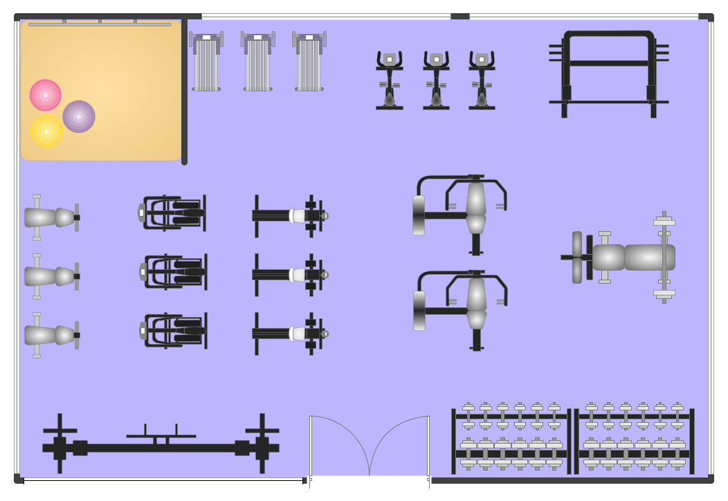
Fitness Plans
- Power socket outlet layout | Network Layout Floor Plans | Power ...
- Power socket outlet layout
- Three Phase Industrial Socket Outlet Symbol
- Design elements - Outlets | Cafe electrical floor plan | Network ...
- Electrical Symbols, Electrical Diagram Symbols | How To use House ...
- Power socket outlet layout | Design elements - Electrical and ...
- Electrical Outlet Visio Stencils
- Cafe electrical floor plan | Layout Diagram On Power System
- How To use House Electrical Plan Software | Symbol For Outlet ...
- Cafe electrical floor plan | Design elements - Qualifying | Network ...