Network Diagram Software Physical Network Diagram


"Logical topology, or signal topology, is the arrangement of devices on a computer network and how they communicate with one another. How devices are connected to the network through the actual cables that transmit data, or the physical structure of the network, is called the physical topology. Physical topology defines how the systems are physically connected. It represents the physical layout of the devices on the network. The logical topology defines how the systems communicate across the physical topologies.
Logical topologies are bound to network protocols and describe how data is moved across the network. ...
EXAMPLE : twisted pair Ethernet is a logical bus topology in a physical star topology layout. while IBM's token ring is a logical ring topology, it is physically set up in star topology." [Logical topology. Wikipedia]
This Cisco logical computer network diagram example was created using the ConceptDraw PRO diagramming and vector drawing software extended with the Cisco Network Diagrams solution from the Computer and Networks area of ConceptDraw Solution Park.
Logical network topology diagram

"At different scales diagrams may represent various levels of network granularity. At the LAN level, individual nodes may represent individual physical devices, such as hubs or file servers, while at the WAN level, individual nodes may represent entire cities. In addition, when the scope of a diagram crosses the common LAN/ MAN/ WAN boundaries, representative hypothetical devices may be depicted instead of showing all actually existing nodes. For example, if a network appliance is intended to be connected through the Internet to many end-user mobile devices, only a single such device may be depicted for the purposes of showing the general relationship between the appliance and any such device." [Computer network diagram. Wikipedia]
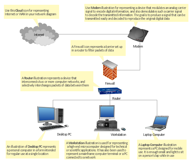
The physical LAN and WAN diagram template for the ConceptDraw PRO diagramming and vector drawing software is included in the Computer and Networks solution from the Computer and Networks area of ConceptDraw Solution Park.
The physical LAN and WAN diagram template for the ConceptDraw PRO diagramming and vector drawing software is included in the Computer and Networks solution from the Computer and Networks area of ConceptDraw Solution Park.
Physical LAN and WAN diagram template
"Physical topology refers to the placement of the network's various components, including device location and cable installation...
The shape of the cabling layout used to link devices is called the physical topology of the network. This refers to the layout of cabling, the locations of nodes, and the interconnections between the nodes and the cabling. The physical topology of a network is determined by the capabilities of the network access devices and media, the level of control or fault tolerance desired, and the cost associated with cabling or telecommunications circuits." [Network topology. Wikipedia]
This physical LAN diagram example was created using the ConceptDraw PRO diagramming and vector drawing software extended with the Computer and Networks solution from the Computer and Networks area of ConceptDraw Solution Park.
LAN physical topology

Used Solutions
Network Gateway Router

"The Ethernet physical layer is the physical layer component of the Ethernet family of computer network standards.
The Ethernet physical layer evolved over a considerable time span and encompasses quite a few physical media interfaces and several magnitudes of speed. The speed ranges from 1 Mbit/ s to 100 Gbit/ s, while the physical medium can range from bulky coaxial cable to twisted pair and optical fiber. In general, network protocol stack software will work similarly on all physical layers.
10-gigabit Ethernet was already used in both enterprise and carrier networks by 2007, with 40 Gbit/ s and 100 Gbit/ s Ethernet ratified. ...
Many Ethernet adapters and switch ports support multiple speeds, using autonegotiation to set the speed and duplex for the best values supported by both connected devices. If auto-negotiation fails, a multiple-speed device will sense the speed used by its partner, but will assume half-duplex. A 10/ 100 Ethernet port supports 10BASE-T and 100BASE-TX. A 10/ 100/ 1000 Ethernet port supports 10BASE-T, 100BASE-TX, and 1000BASE-T." [Ethernet physical layer. Wikipedia]
The LAN equipment and cabling layout floorplan example "Ethernet local area network layout floor plan" was created using the ConceptDraw PRO diagramming and vector drawing software extended with the Network Layout Floor Plans solution from the Computer and Networks area of ConceptDraw Solution Park.
Ethernet LAN layout floorplan

- Diagram Physical Topologies | Hotel Network Topology Diagram ...
- Network Diagram Software Physical Network Diagram | Physical ...
- Network Diagram Software Physical Network Diagram ...
- Diagram Physical Topologies | Network Diagram Software Physical ...
- Network Diagram Software Physical Network Diagram
- Network Diagram Software Physical Network Diagram | Diagram ...
- Network Diagram Examples | Physical LAN and WAN diagram ...
- Network Diagram Software Physical Network Diagram | Network ...
- Hotel Network Topology Diagram | Diagram Physical Topologies ...
- Logical network topology diagram | Physical network . Computer and ...
- Physical And Logical Network Layout
- Logical network topology diagram | Diagram Physical Topologies ...
- Star Network Topology | Bus Network Topology | Network ...
- Diagram Physical Topologies | Network Topologies | Star Network ...
- Hotel Network Topology Diagram
- Diagram Physical Topologies | Star Network Topology | Logical ...
- Logical network topology diagram | Star Network Topology ...
- Logical Network Diagram Vs Physical Network Diagram
- Physical Network Topologies
- Building Phyiscal Network Layout