Entity Relationship Diagram - ERD - Software for Design Crows Foot ER Diagrams
_Win_Mac.png)

Example of DFD for Online Store (Data Flow Diagram)


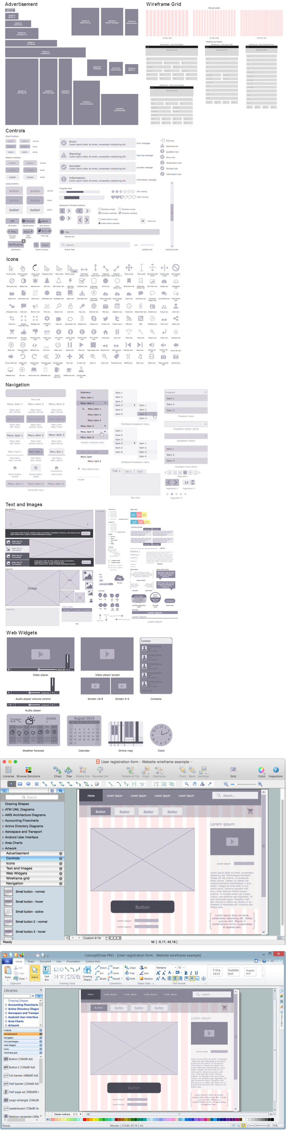
Wireframing
UML Use Case Diagram Example - Estate Agency

Diagramming Software for Design UML Use Case Diagrams


Data Flow Diagrams

Interaction Overview Diagram

How to Help Customers be More Productive
UML Class Diagram Generalization Example UML Diagrams

Entity Relationship Diagram Software Engineering

- Entity-Relationship Diagram ( ERD ) | E R Diagram Online Shopping
- Package Diagram For Online Student Registration System
- Online Shopping Wireframes
- Online Shopping Using Class Diagram And Statechart Diagram
- Erd For Login Website
- Example of DFD for Online Store (Data Flow Diagram) DFD ...
- Entity-Relationship Diagram ( ERD ) | Er Diagram Of Website
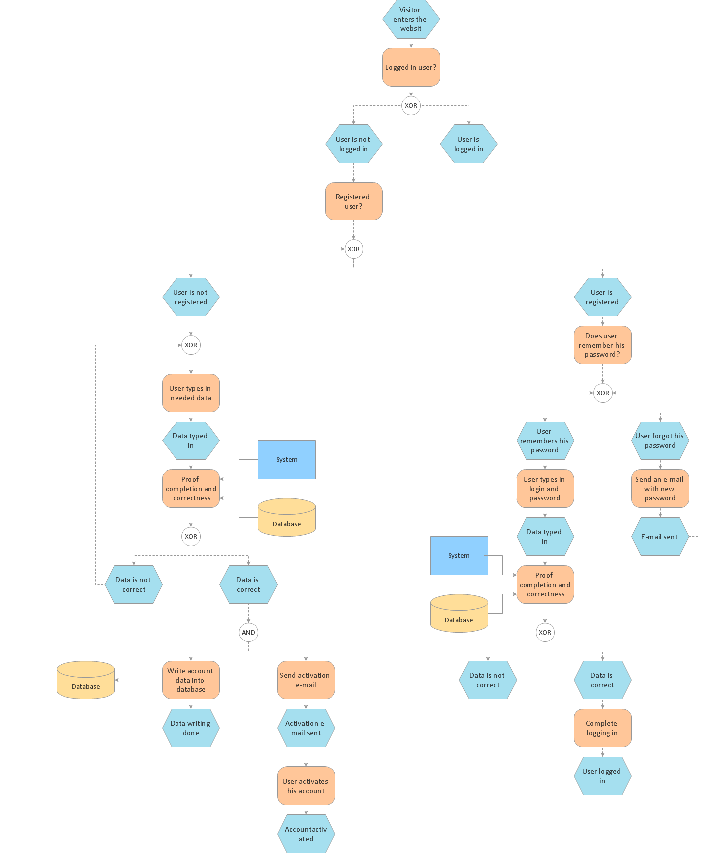
- Login and registration processing | Login and registration ...
- Entity-Relationship Diagram ( ERD ) | Active Directory Diagrams ...
- ER Diagram For User Register And Login