Process Flow Diagram Symbols

Mechanical Drawing Symbols

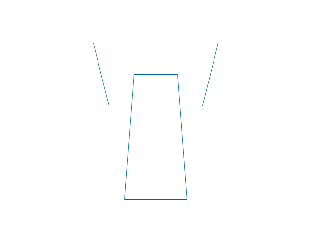
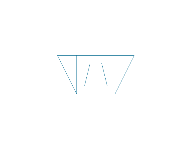
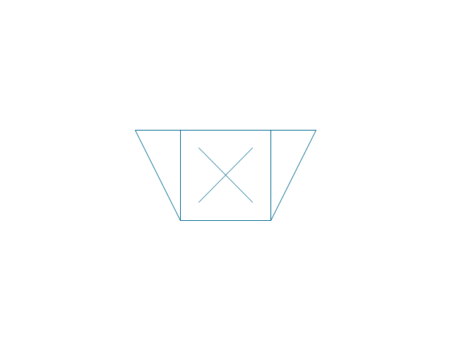
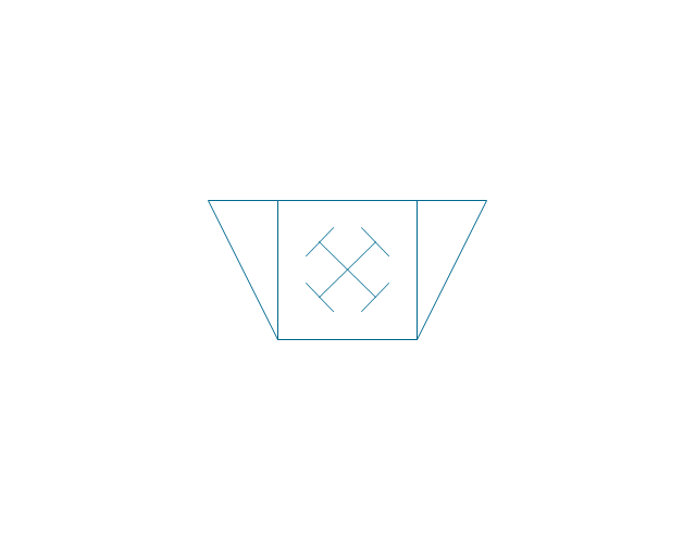
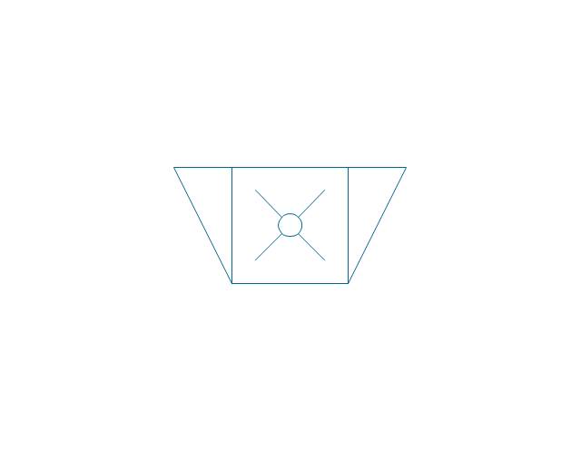
The vector stencils library "Heating equipment" contains 42 symbols of regenerators, intercoolers, heaters, and condensers.
Use these shapes for drawing cooling systems, heat recovery systems, thermal, heat transfer and mechanical design, and process flow diagrams (PFD) in the ConceptDraw PRO software extended with the Chemical and Process Engineering solution from the Chemical and Process Engineering area of ConceptDraw Solution Park.
www.conceptdraw.com/ solution-park/ engineering-chemical-process
Heat exchanger 3

Heat exchanger 1

Heat exchanger 2

Tube bundle, floating head

U-Tube bundle

Tube bundle

Shell and tube

Kettle reboiler

Plate type

Finned tube

Double pipe type

Oil burner

Boiler

Fired heater

Cooling tower 2

Cooling tower 1

Cooling tower 3

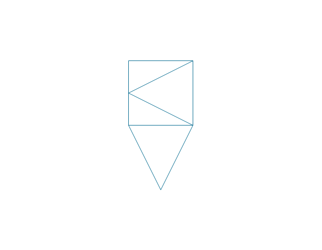
Condenser

Automatic stoker

Refrigerator

Direct refrigerator

Indirect refrigerator

Evaporative condenser

Condenser (air cooled)
-heating-equipment---vector-stencils-library.png--diagram-flowchart-example.png)
Oil separator

Chilling evaporator

Air cooling evaporator

Extractor hood (slot)
-heating-equipment---vector-stencils-library.png--diagram-flowchart-example.png)
Extractor hood (open)
-heating-equipment---vector-stencils-library.png--diagram-flowchart-example.png)
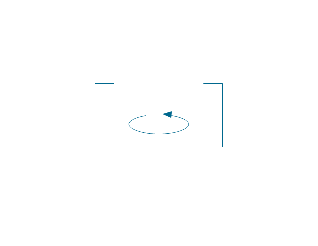
Autoclave (propeller)
-heating-equipment---vector-stencils-library.png--diagram-flowchart-example.png)
Autoclave (anchor)
-heating-equipment---vector-stencils-library.png--diagram-flowchart-example.png)
Autoclave (helical)
-heating-equipment---vector-stencils-library.png--diagram-flowchart-example.png)
Autoclave with motor (helical)
-heating-equipment---vector-stencils-library.png--diagram-flowchart-example.png)
Autoclave with motor (anchor)
-heating-equipment---vector-stencils-library.png--diagram-flowchart-example.png)
Autoclave with motor (propeller)
-heating-equipment---vector-stencils-library.png--diagram-flowchart-example.png)
Fan blades horizontal

Fan blades vertical

Fan blades (4)
-heating-equipment---vector-stencils-library.png--diagram-flowchart-example.png)
Triple fan blades

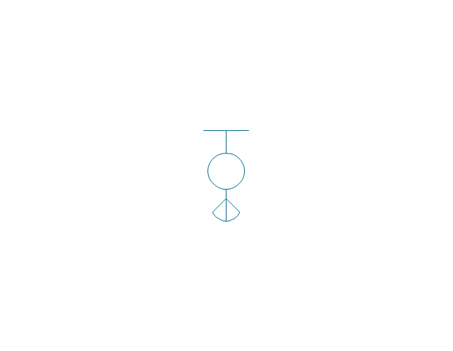
Air-blown cooler

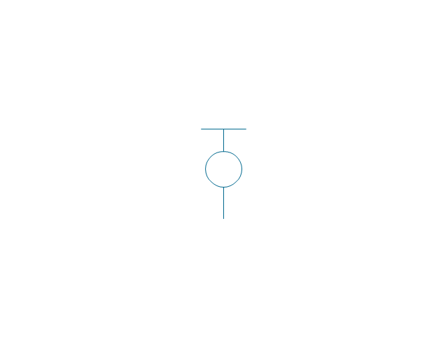
Condenser

Heater / Cooler

Electrical Symbols — Qualifying

Cross-Functional Flowchart


The vector stencils library "Fluid power equipment" contains 113 symbols of hydraulic and pneumatic equipment including pumps, motors, air compressors, cylinders, meters, gauges, and actuators.
Use it to design fluid power and hydraulic control systems in the ConceptDraw PRO diagramming and vector drawing software extended with the Mechanical Engineering solution from the Engineering area of ConceptDraw Solution Park.
www.conceptdraw.com/ solution-park/ engineering-mechanical
Use it to design fluid power and hydraulic control systems in the ConceptDraw PRO diagramming and vector drawing software extended with the Mechanical Engineering solution from the Engineering area of ConceptDraw Solution Park.
www.conceptdraw.com/ solution-park/ engineering-mechanical
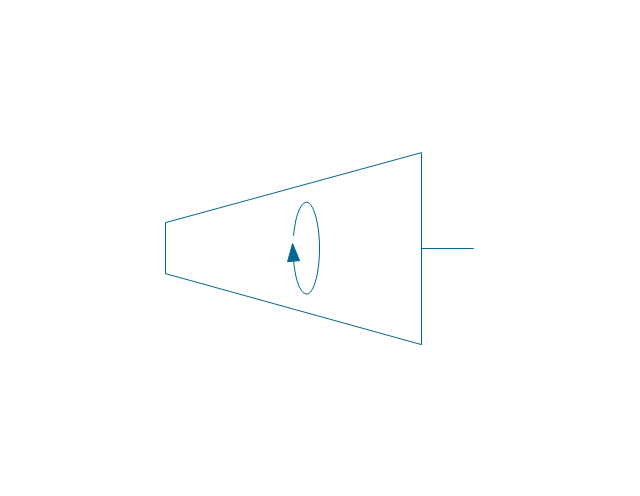
Actuator (semi-rotary), pneumatic
,-pneumatic-fluid-power-equipment---vector-stencils-library.png--diagram-flowchart-example.png)
Actuator (semi-rotary), hydraulic
,-hydraulic-fluid-power-equipment---vector-stencils-library.png--diagram-flowchart-example.png)
Drive unit, pneumatic

Drive unit, hydraulic

Sgl-act. cylinder, pneum., left spring

Sgl-act. cylinder, pneum., right spring

Sgl-act. cylinder, pneumatic

Sgl-act. cylinder, hydr., left spring

Sgl-act. cylinder, hydr., right spring

Sgl-act. cylinder, hydraulic

Dbl-act. cylinder, pneumatic

Dbl-act. cylinder, pneum., sgl cushion

Dbl-act. cylinder, pneum., dbl cushion

Dbl-act. cylinder, pneum., adjustable

Dbl-act. cylinder, pneum., sgl cushion, adj.

Dbl-act. cylinder, pneum., dbl cushion, adj.

Dbl-act. cylinder, hydraulic

Dbl-act. cylinder, hydr., sgl cushion

Dbl-act. cylinder, hydr., dbl cushion

Dbl-act. cylinder, hydr., adjustable

Dbl-act. cylinder, hydr., sgl cushion, adj.

Dbl-act. cylinder, hydr., dbl cushion, adj.

Dbl-act. cylinder, magnetic

Dbl-act. cylinder, magn., sgl cushion

Dbl-act. cylinder, magn., dbl cushion

Dbl-act. cylinder, magn., adjustable

Dbl-act. cylinder, magn., sgl cushion, adj.

Dbl-act. cylinder, magn., dbl cushion, adj.

Dbl-act. dbl-end. cylinder, pneumatic

Dbl-act. dbl-end. cylinder, pneum., sgl cushion

Dbl-act. dbl-end. cylinder, pneum., dbl cushion

Dbl-act. dbl-end. cylinder, pneum., adjustable

Dbl-act. dbl-end. cylinder, pneum., sgl cushion, adj.

Dbl-act. dbl-end. cylinder, pneum., dbl cushion, adj.

Dbl-act. dbl-end. cylinder, hydraulic

Dbl-act. dbl-end. cylinder, hydr., sgl cushion

Dbl-act. dbl-end. cylinder, hydr., dbl cushion

Dbl-act. dbl-end. cylinder, hydr., adjustable

Dbl-act. dbl-end. cylinder, hydr., sgl cushion, adj.

Dbl-act. dbl-end. cylinder, hydr., dbl cushion, adj.

Telescopic cylinder, pneum., dbl-act.

Telescopic cylinder, hydr., dbl-act.

Telescopic cylinder, pneum., sgl-act.

Telescopic cylinder, hydr., sgl-act.

Actuator, hydraulic-pneumatic

Actuator, pneumatic-hydraulic

Intensifier, pneumatic

Intensifier, hydraulic

Intensifier, hydraulic-pneumatic

Intensifier, pneumatic-hydraulic

Intensifier, pneumatic-hydraulic

Intensifier, hydraulic-pneumatic

Actuator, pneumatic-hydraulic

Actuator, hydraulic-pneumatic

Accumulator

Accumulator, gas loaded

Accumulator, spring loaded

Accumulator, auxiliary gas bottle

Air receiver

Energy source, pneumatic

Energy source, hydraulic

Energy source, electric motor

Energy source, non-electric prime mover

Vented reservoir

Sealed reservoir

Filter

Filter, magnetic element

Filter, contamination indicator

Automatic drain filter separator

Manual drain filter separator

Separator, automatic drain

Separator, manual drain

Air dryer

Lubricator

Air service unit, filter, separator

Air service unit, separator

Air service unit, filter

Air service unit

Liquid cooler

Gas cooler

Cooler

Liquid heater

Gas heater

Heater

Liquid temperature controller

Gas temperature controller

Temperature controller

Liquid temperature controller 2

Gas temperature controller 2

Temperature controller 2

Pressure indicator

Pressure gauge

Differential pressure gauge

Thermometer

Liquid level measuring instrument

Flow indicator

Flow meter

Integrating flow meter

Tachometer

Torque measurement equipment

Pressure switch

Limit switch

Transducer

Pulse counter

Pulse counter 2

Silencer

Drain (inlet below fluid, drain line)
-fluid-power-equipment---vector-stencils-library.png--diagram-flowchart-example.png)
Drain (inlet below fluid, return line)
-fluid-power-equipment---vector-stencils-library.png--diagram-flowchart-example.png)
Drain (inlet above fluid, drain line)
-fluid-power-equipment---vector-stencils-library.png--diagram-flowchart-example.png)
Drain (inlet above fluid, return line)
-fluid-power-equipment---vector-stencils-library.png--diagram-flowchart-example.png)
Oil tank

Oil tank, empty

Air compressor

The vector stencils library "Valves and fittings" contains 104 symbols of valve components.
Use these icons for drawing industrial piping systems; process, vacuum, and fluids piping; hydraulics piping; air and gas piping; materials distribution; and liquid transfer systems.
"A valve is a device that regulates, directs or controls the flow of a fluid (gases, liquids, fluidized solids, or slurries) by opening, closing, or partially obstructing various passageways. Valves are technically valves fittings, but are usually discussed as a separate category. In an open valve, fluid flows in a direction from higher pressure to lower pressure.
The simplest, and very ancient, valve is simply a freely hinged flap which drops to obstruct fluid (gas or liquid) flow in one direction, but is pushed open by flow in the opposite direction. This is called a check valve, as it prevents or "checks" the flow in one direction. ...
Valves are found in virtually every industrial process, including water & sewage processing, mining, power generation, processing of oil, gas & petroleum, food manufacturing, chemical & plastic manufacturing and many other fields. ...
Valves may be operated manually, either by a handle, lever, pedal or wheel. Valves may also be automatic, driven by changes in pressure, temperature, or flow. These changes may act upon a diaphragm or a piston which in turn activates the valve, examples of this type of valve found commonly are safety valves fitted to hot water systems or boilers.
More complex control systems using valves requiring automatic control based on an external input (i.e., regulating flow through a pipe to a changing set point) require an actuator. An actuator will stroke the valve depending on its input and set-up, allowing the valve to be positioned accurately, and allowing control over a variety of requirements." [Valve. Wikipedia]
The example "Design elements - Valves and fittings" was created using the ConceptDraw PRO diagramming and vector drawing software extended with the Chemical and Process Engineering solution from the Engineering area of ConceptDraw Solution Park.
Valves and fittings symbols

The vector stencils library "Industrial equipment" contains 81 symbols of pumps, compressors, fans, turbines, and power generators.
Use these shapes to design pumping systems, air and fluid compression systems, and industrial process diagrams in the ConceptDraw PRO software extended with the Chemical and Process Engineering solution from the Chemical and Process Engineering area of ConceptDraw Solution Park.
www.conceptdraw.com/ solution-park/ engineering-chemical-process
Breaker
Crusher
Crusher coarse
Crusher medium

Crusher fine

Roll crusher

Hammer crusher

Crusher single load

Crusher hammer

Crusher impact
Crusher jaw

Crusher high-speed roller

Crusher cone

Crusher cone 2
Crusher general
Crusher hammer 2
Crusher impact 2
Crusher jaw 2
Crusher roller
Ball mill

Mill general

Mill hammer

Mill impact
Mill jet
Mill roller
Mill vibrator
Mixer

Mixer general

Mixer rotary

Mixer can
Mixer fluidized

Kneader

Kneader general

Kneader wheel
Kneader ball

Kneader rolling

Kneader blade

Blender

Double blender
Fluid separator general

Fluid separator wet

Fluid separator dry

Fluid separator gravitation

Fluid separator inertial

Fluid separator centrifugal

Filter 1
Filter 2

Rotary filter

Screen

Electromagnet
Cyclone 1
Cyclone 2
Centrifuge general

Centrifuge dehydrator
Centrifuge submersion
Centrifuge 2

Briquetting machine standard
Briquetting machine

Prill tower

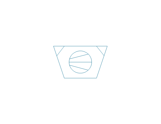
Dryer

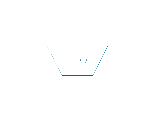
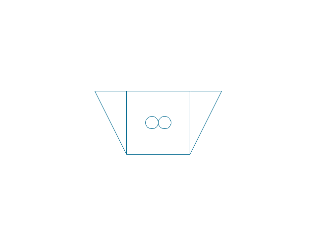
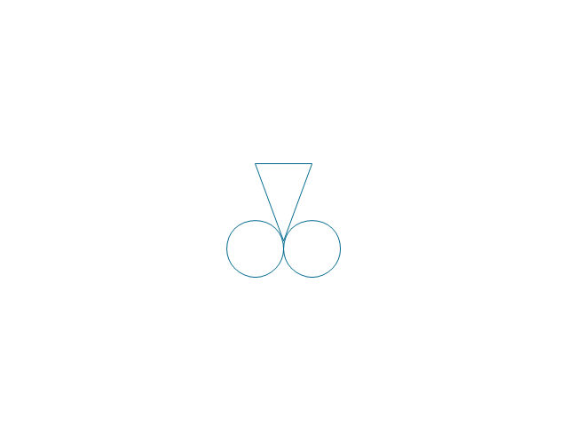
Conveyor 2 circles 2 lines

Conveyor 2 circles 1 line

Conveyor 1 circle 2 lines

Conveyor 1 circle 1 line

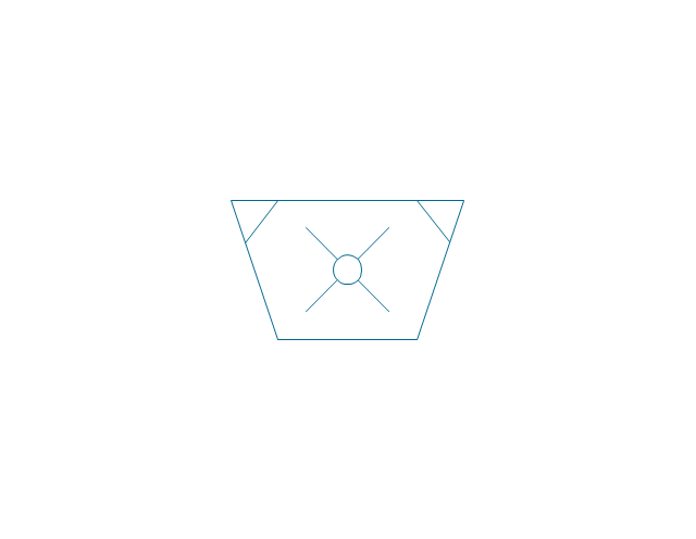
Conveyor wheel

Boom loader
Scraper conveyor
Screw conveyor
Screw conveyor 2
Elevator 1
Elevator 2
Skip hoist
Overhead conveyor
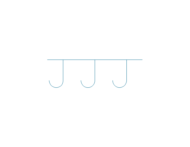
Overhead conveyor with hooks
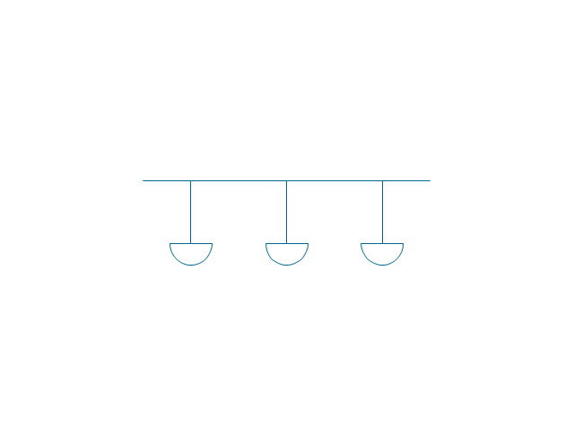
Overhead conveyor with buckets
Hoist
Hoist with hook

Hoist with grab
Electric motor
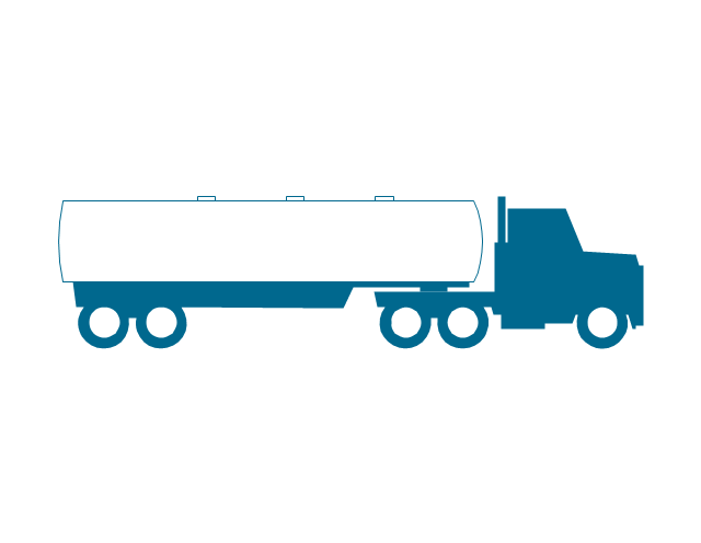
Tank truck
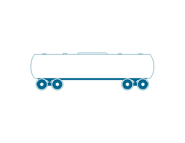
Tank car
Technical Drawing Software

 Mechanical Engineering
This solution extends ConceptDraw DIAGRAM.9 mechanical drawing software (or later) with samples of mechanical drawing symbols, templates and libraries of design elements, for help when drafting mechanical engineering drawings, or parts, assembly, pneumatic,
- Electrostatic Separator Symbol Pfd
- Intercooler Symbols
- Tube Heater Oil Water Symbol
- Process Flow Diagram Symbols | Chemical and Process ...
- Mechanical Drawing Symbols | Design elements - Fluid power ...
- Process Flow Diagram Symbols | Design elements - Heating ...
- Symbol Of Condenser
- Reboiler Symbol
- Symbol Of Direct Fired Heaters