 Network Layout Floor Plans
Network Layout Floor Plans solution extends ConceptDraw DIAGRAM software functionality with powerful tools for quick and efficient documentation the network equipment and displaying its location on the professionally designed Network Layout Floor Plans. Never before creation of Network Layout Floor Plans, Network Communication Plans, Network Topologies Plans and Network Topology Maps was not so easy, convenient and fast as with predesigned templates, samples, examples and comprehensive set of vector design elements included to the Network Layout Floor Plans solution. All listed types of plans will be a good support for the future correct cabling and installation of network equipment.
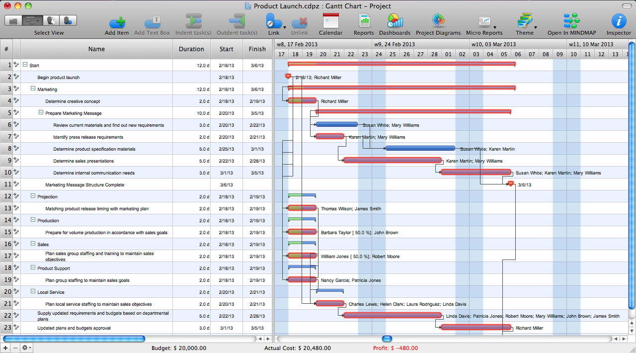
ConceptDraw PROJECT Project Management Software Tool
Activity on Node Network Diagramming Tool

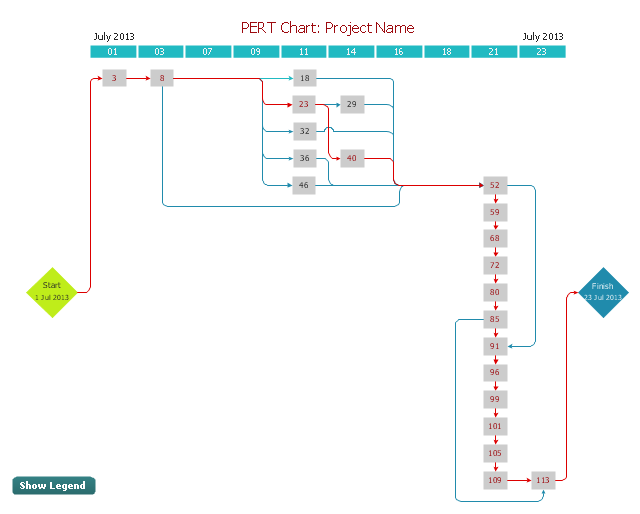
Activity Network (PERT) Chart

Local area network (LAN). Computer and Network Examples
 diagram")

"A project network is a graph (flow chart) depicting the sequence in which a project's terminal elements are to be completed by showing terminal elements and their dependencies.
... the project network shows the "before-after" relations.
The most popular form of project network is activity on node, the other one is activity on arrow.
The condition for a valid project network is that it doesn't contain any circular references." [Project network. Wikipedia]
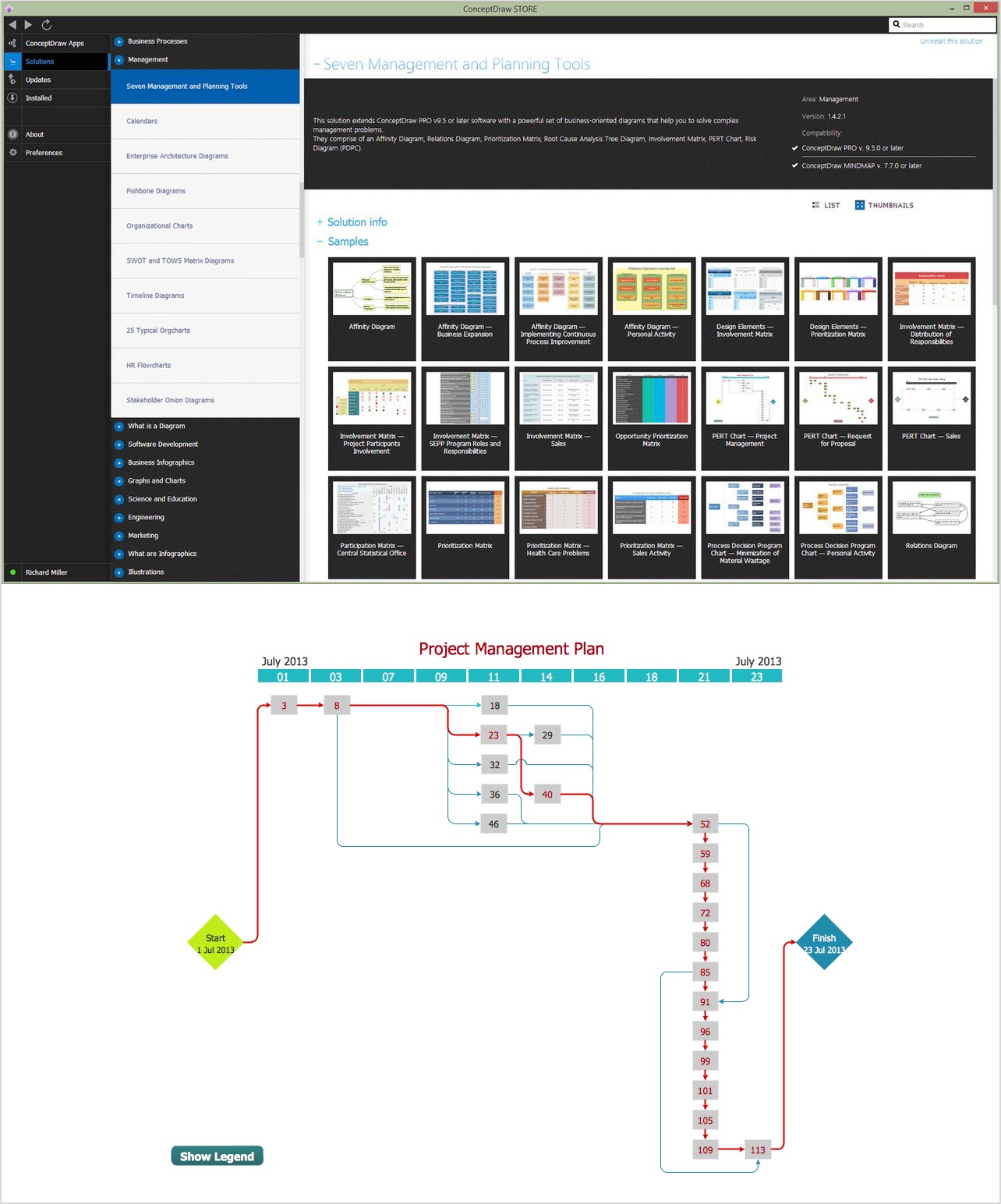
The PERT chart example "Project management plan" was created using the ConceptDraw PRO diagramming and vector drawing software extended with the solution "Seven Management and Planning Tools" from the Management area of ConceptDraw Solution Park.
... the project network shows the "before-after" relations.
The most popular form of project network is activity on node, the other one is activity on arrow.
The condition for a valid project network is that it doesn't contain any circular references." [Project network. Wikipedia]
The PERT chart example "Project management plan" was created using the ConceptDraw PRO diagramming and vector drawing software extended with the solution "Seven Management and Planning Tools" from the Management area of ConceptDraw Solution Park.
PERT
Legend
Computer Networking Tools List

Program Evaluation and Review Technique (PERT) with ConceptDraw DIAGRAM

CORRECTIVE ACTIONS PLANNING. PERT Chart

Personal Memory Assistant

- A Task Network Diagram In Soft Project Management
- Project plan timeline - Request for proposal (RFP) | Activity Network ...
- PERT chart - Project management plan | ConceptDraw PROJECT ...
- PERT chart - Project management plan | Network Diagramming ...
- Pert Chart Project Examples
- PERT chart - Project management plan | Project — Working With ...
- Pert Chart Activities Network Diagram For Project Management
- PERT chart - Project management plan
- Gant Chart in Project Management | Physical Security Plan ...