Electrical Symbols, Electrical Diagram Symbols

Building Drawing. Design Element: Piping Plan


Electrical Drawing Software and Electrical Symbols

Building Drawing Software for Designing Plumbing

The vector stencils library "HVAC ductwork" contains 55 duct and vent symbols of HVAC mechanical components. Use it for drawing HVAC ductwork system diagrams, heating, ventilation, air conditioning, refrigeration, automated building control, and environmental control design in the ConceptDraw PRO diagramming and vector drawing software extended with the HVAC Plans solution from the Building Plans area of ConceptDraw Solution Park.
Rect. duct, closed ends

Rect. duct, open 1 end

Rect. duct, open both ends

Circ. duct, closed ends

Circ. duct, open 1 end

Circ. duct, open both ends

Branch duct, rectangular

Branch duct, circular

Variable bend

Miter bend

Y junction

3 way junction

Junction 1

Beveled junction, rect. duct, rect. branch

Beveled junction, rect. duct, circ. branch

Beveled junction, circ. duct, rect. branch

Beveled junction, circ. duct, circ. branch

Transition, rect. to rect.

Transition, rect. to circ.

Transition, circ. to rect.

Transition, circ. to circ.

Offset transition, rect. to rect.

Offset transition, rect. to circ.

Offset transition, circ. to rect.

Offset transition, circ. to circ.

Flexible connection, rect. duct

Flexible connection, circ. duct

Flexible connection 2, rect. duct

Flexible connection 2, circ. duct

Supply, rect. duct toward

Supply, rect. duct away

Supply, rect. duct, elbow away

Supply, circ. duct toward

Supply, circ. duct away

Supply, circ. duct, elbow away

Return, rect. duct toward

Return, rect. duct away

Return, rect. duct, elbow away

Return, circ. duct toward

Return, circ. duct away

Return, circ. duct, elbow away

Sliding damper, rect. duct

Sliding damper, circ. duct

Damper, ACD

Damper, BD

Damper, FD/AD

Damper, MD

Damper, SD/AD

Vert. duct, rect. duct toward

Vert. duct, rect. duct away

Vert. duct, rect. duct, elbow away

Vert. duct, circ. duct toward

Vert. duct, circ. duct away

Vert. duct, circ. duct, elbow away

VAV box

Building Drawing. Design Element — Plumbing

Building Drawing Software for Design Piping Plan
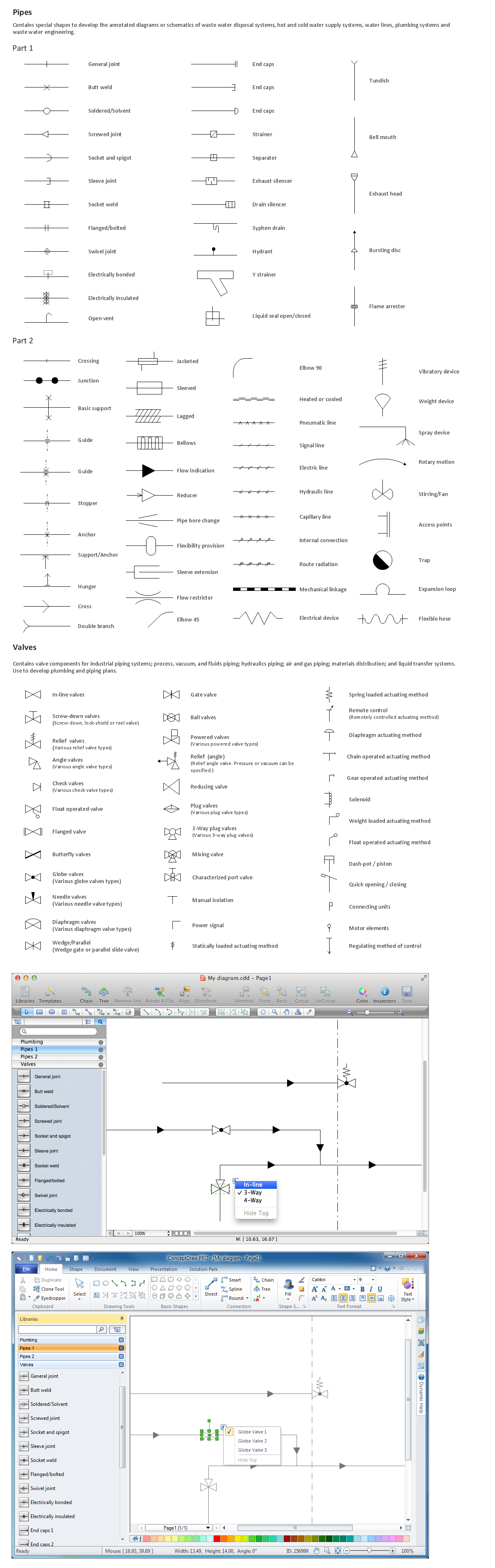
The vector stencils libraries "Pipes 1" and "Pipes 2" contain 28 and 48 pipe, tubing and fitting symbols, respectively.
"A fitting is used in pipe plumbing systems to connect straight pipe or tubing sections, to adapt to different sizes or shapes, and for other purposes, such as regulating or measuring fluid flow. The term plumbing is generally used to describe conveyance of water, gas, or liquid waste in ordinary domestic or commercial environments, whereas piping is often used to describe high-performance (e.g. high pressure, high flow, high temperature, hazardous materials) conveyance of fluids in specialized applications. The term tubing is sometimes used for lighter-weight piping, especially types that are flexible enough to be supplied in coiled form.
Fittings (especially uncommon types) require money, time, materials, and tools to install, so they are a non-trivial part of piping and plumbing systems." [Piping and plumbing fitting. Wikipedia]
Use the design elements libraries "Pipes 1" and "Pipes 2" for drawing plumbing and piping building plans, schematic diagrams, blueprints, or technical drawings of waste water disposal systems, hot and cold water supply systems using the ConceptDraw PRO diagramming and vector drawing software.
The shapes libraries "Pipes 1" and "Pipes 2" are contained in the Plumbing and Piping Plans solution from the Building Plans area of ConceptDraw Solution Park.
Piping symbols
.png--diagram-flowchart-example.png)
Building Drawing Software for Design School Layout

The vector stencils libraries "Pipes 1" and "Pipes 2" contain 28 and 48 pipe, tubing and fitting symbols, respectively.
"Pipe is hollow cylinder used to conduct or transfer fluids (liquids and gases) from one place to other place. The main difference between pipe and tube is the critical dimension used to describe the pipe size or the tube size. For pipe, internal diameter (ID) roughly corresponds to the nominal pipe size for standard wall thickness. For tube, the outer diameter (OD) closely corresponds to the tube size. In current European standards pipes and tubes are nowadays described as outside diameter by wall thickness. The three standard types of pipe ends used in the piping industriesare; Plain Ends (PE), Threaded Ends (TE) and Beveled Ends (BE). In the past, many types of material have been used in conveying water from one point to another. Masonry and wood were probably the first materials used. Plastics are the newest, and are now being used quite extensively." [Piping. Wikipedia]
Use the design elements libraries "Pipes 1" and "Pipes 2" for drawing plumbing and piping building plans, schematic diagrams, blueprints, or technical drawings of waste water disposal systems, hot and cold water supply systems using the ConceptDraw PRO diagramming and vector drawing software.
The shapes libraries "Pipes 1" and "Pipes 2" are contained in the Plumbing and Piping Plans solution from the Building Plans area of ConceptDraw Solution Park.
Piping symbols
.png--diagram-flowchart-example.png)
- Mechanical Drawing Symbols | Machanical Fitter Drawings
- Mechanical Fitting Drawing Pdf
- Mechanical Drawing Symbols | Machenical Fitter Drawings
- Plumbing and Piping Plans | Mechanical Fitting Diagrams
- Mechanical Fitter Diagram
- Fitter Mechanical Symbol
- Fitter Sembol
- Mechanical Drawing Symbols | How To use House Electrical Plan ...
- Pipe Fitter All Drawing Symbols
- Modern Electric Fitting Plan