Mechanical Drawing Symbols

The vector stencils library "Bearings" contains 59 symbols of ball bearings, roller bearings, shafts, springs, gears, hooks, spindles, and keys.
Use it to design engineering drawings of machine tools and mechanical devices in the ConceptDraw PRO diagramming and vector drawing software extended with the Mechanical Engineering solution from the Engineering area of ConceptDraw Solution Park.
www.conceptdraw.com/ solution-park/ engineering-mechanical
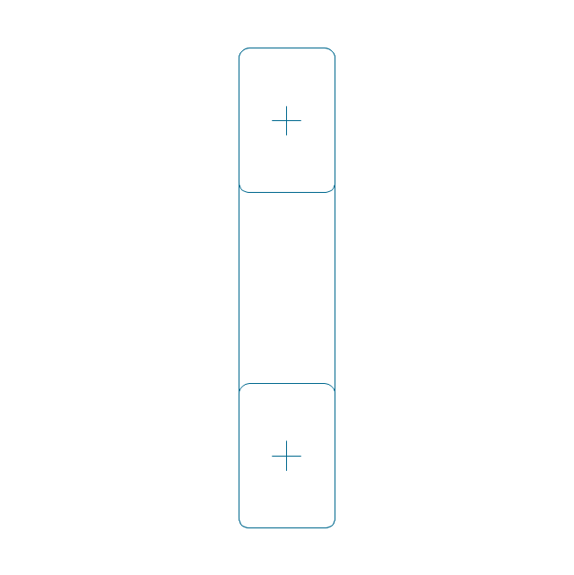
Through hole

Threaded hole 3
Threaded hole 4
Rolling bearings 2
Rolling bearings
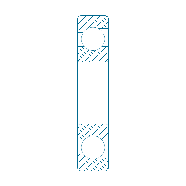
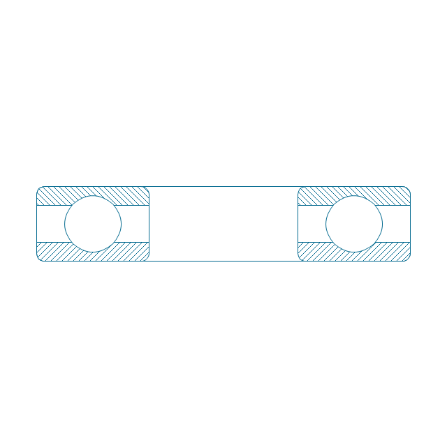
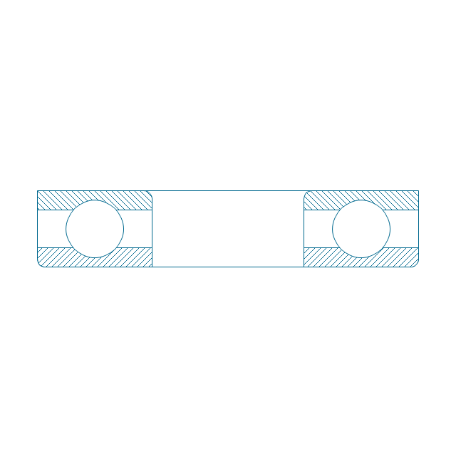
Deep groove ball bearing, hatched
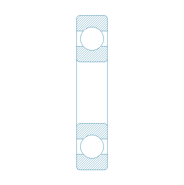
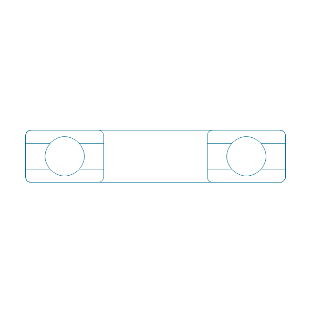
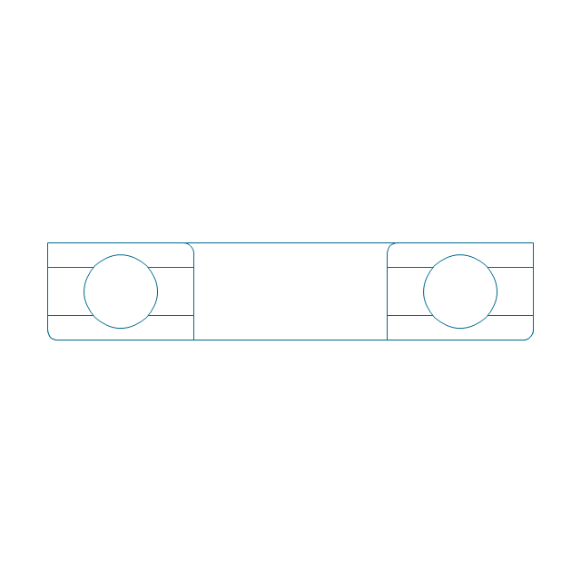
Deep groove ball bearing, unhatched
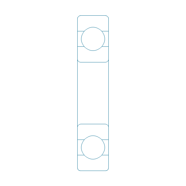
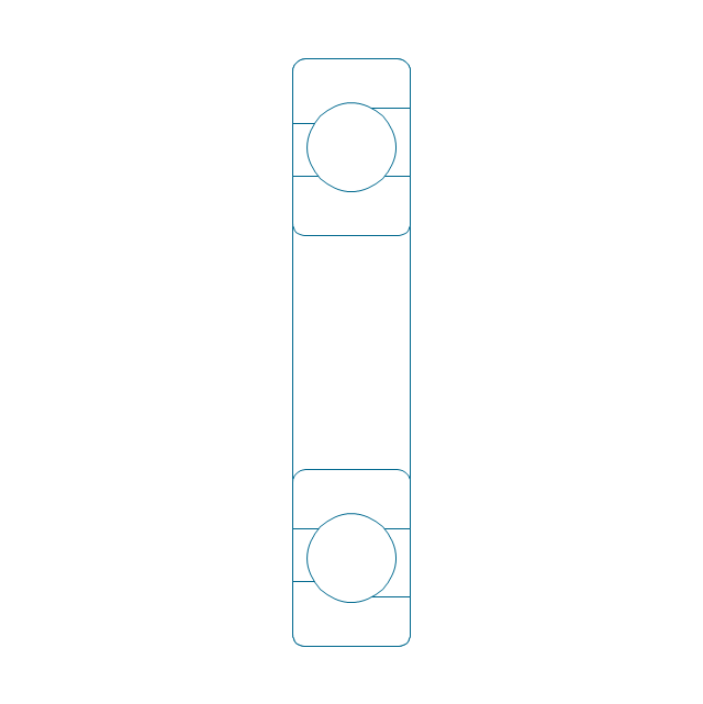
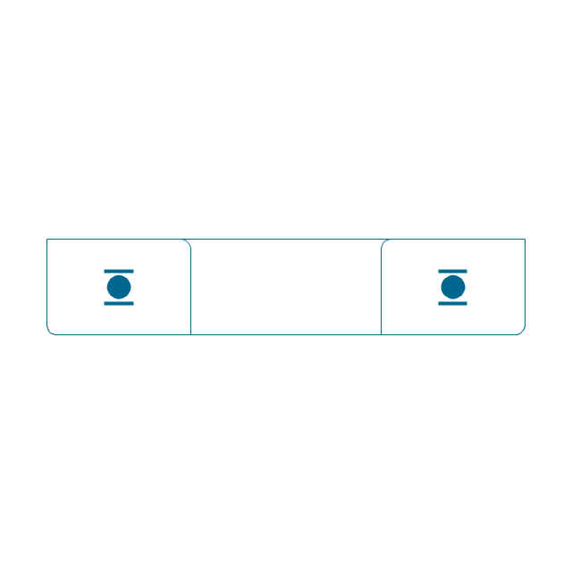
Deep groove ball bearing, simpl.
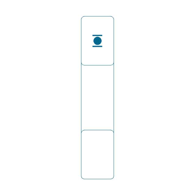
Angular contact ball bearing, simpl.
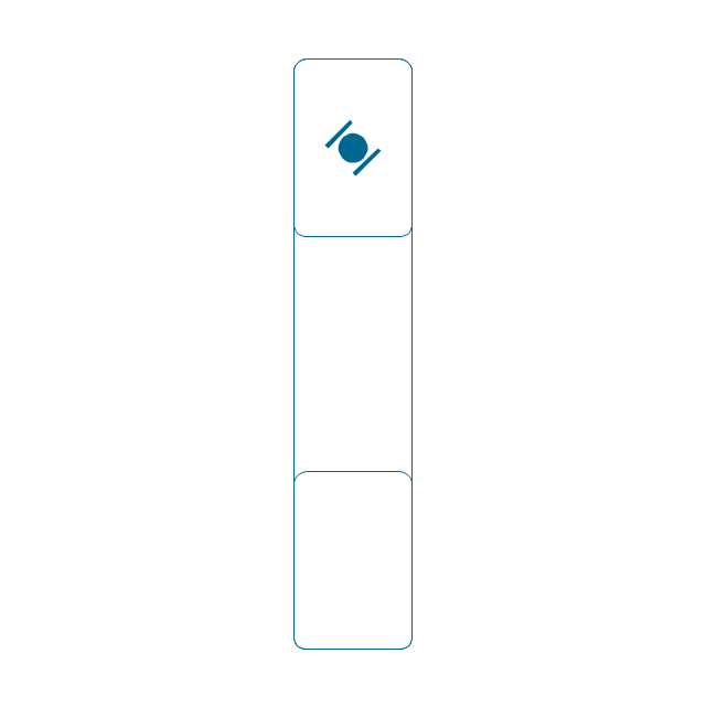
Angular contact ball bearing, unhatched
Angular contact ball bearing, hatched
Angular contact ball bearing dbl, unhatched
Angular contact ball bearing dbl, hatched
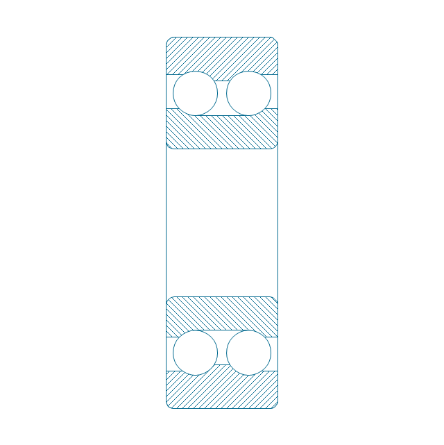
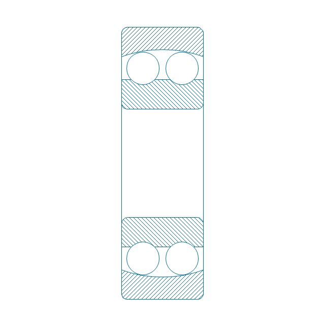
Self align. dbl ball bearing, hatched
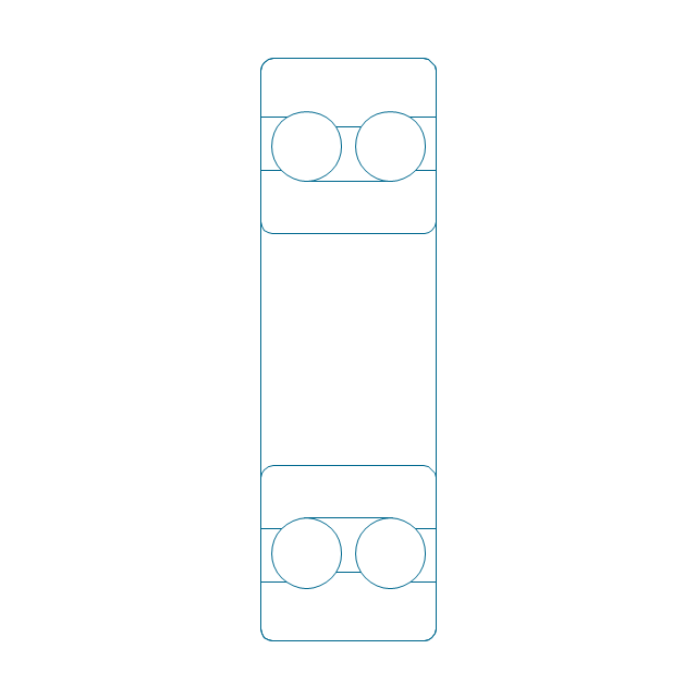
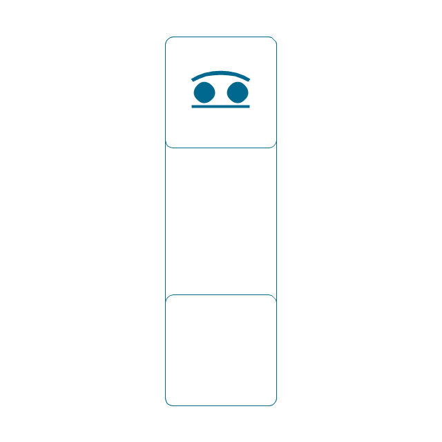
Self align. dbl bearing, simpl.
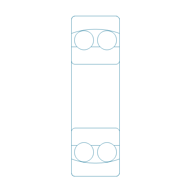
Self align. dbl ball bearing, unhatched
Thrust ball bearing, hatched
Thrust ball bearing, unhatched
Thrust ball bearing, simpl.
Thrust ball bearing, hatched 2
Thrust ball bearing, unhatched 2
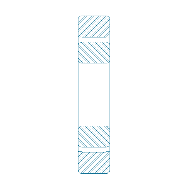
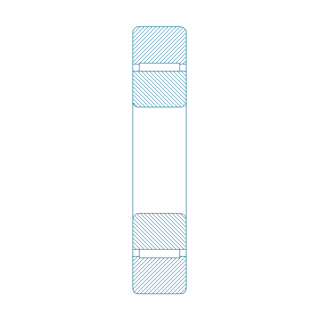
Cylindrical roller bearing, hatched
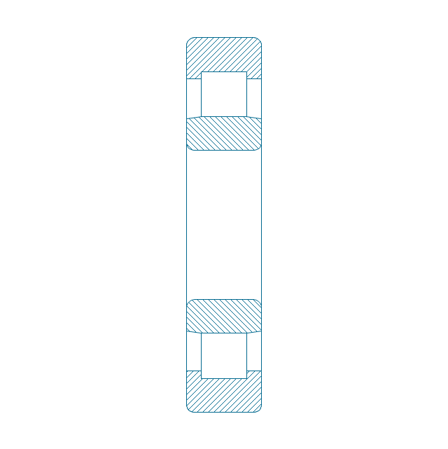
Cylindrical roller bearing, unhatched
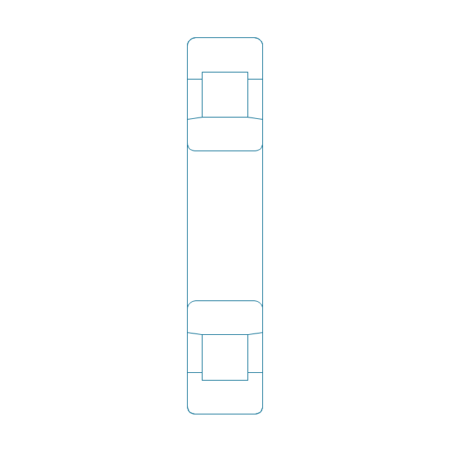
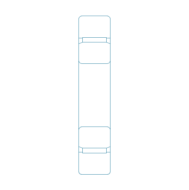
Cylindrical roller bearing, simpl.
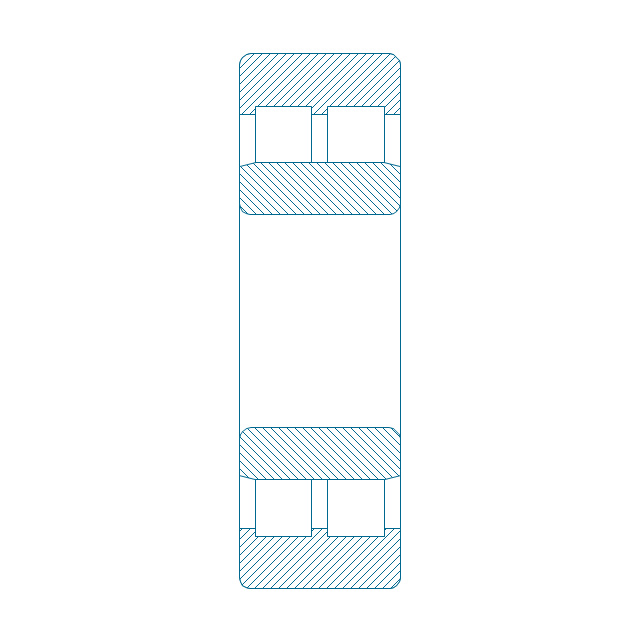
Cylindrical roller bearing dbl, simpl.
Cylindrical roller bearing dbl, unhatched
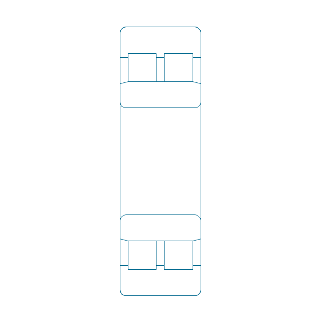
Cylindrical roller bearing dbl, hatched
Taper roller bearing, hatched
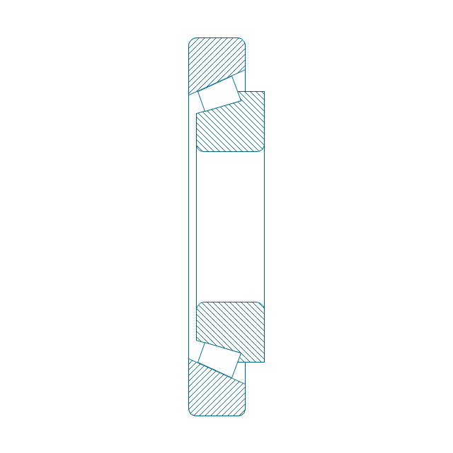
Taper roller bearing, unhatched
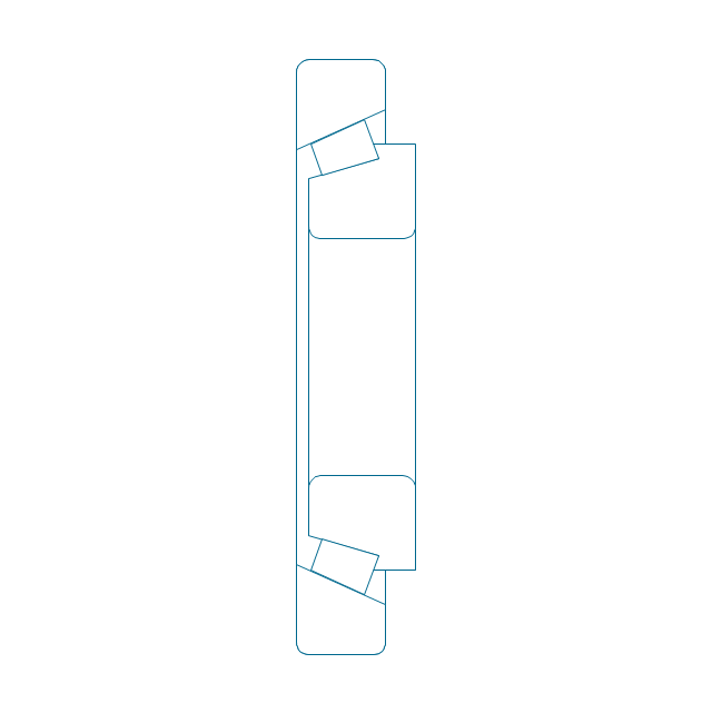
Taper roller bearing, simpl.
Needle roller bearing, hatched
Needle roller bearing, hatched 2
Needle roller bearing, unhatched
Needle roller bearing, unhatched 2
Needle roller bearing, simpl.
Spher. roller bearing dbl, hatched 2
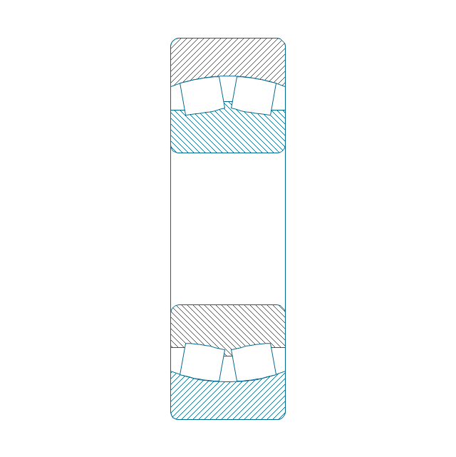
Spher. roller bearing dbl, hatched
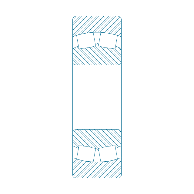
Spher. roller bearing dbl, unhatched
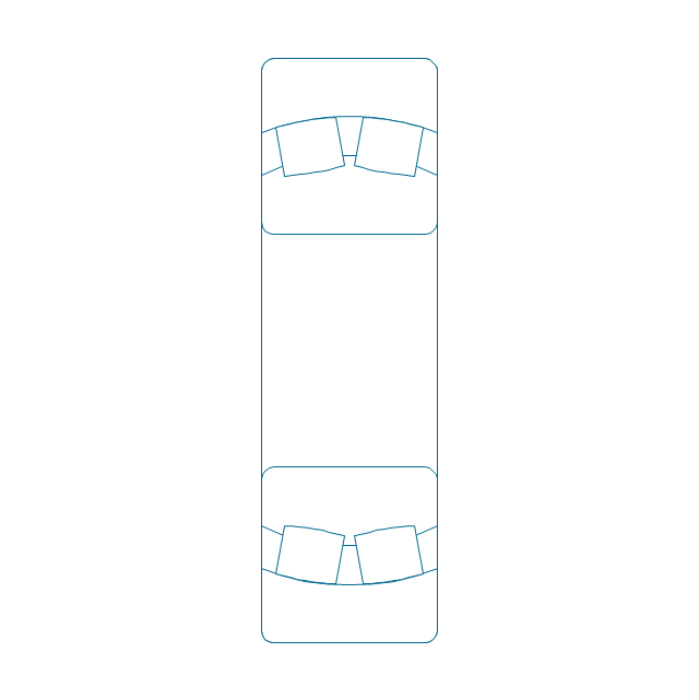
Spher. roller bearing dbl, unhatched 2
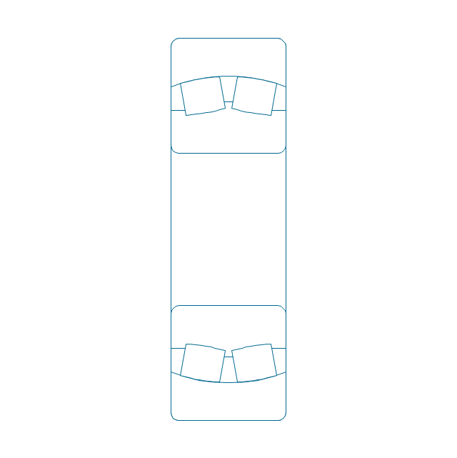
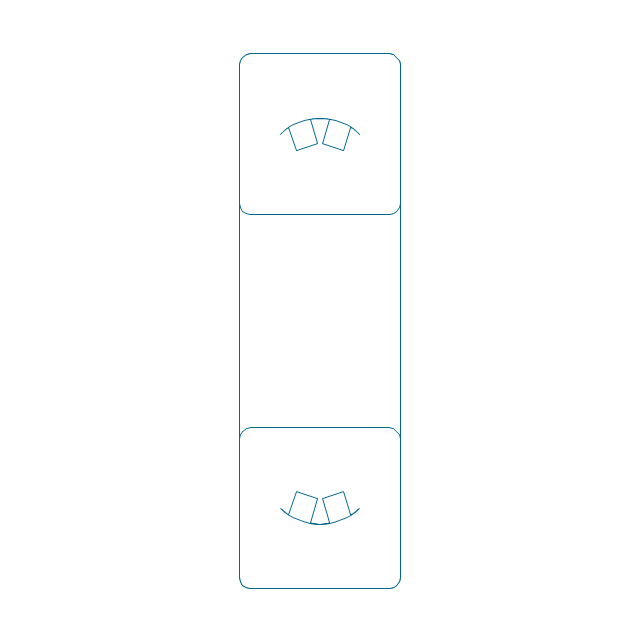
Spher. roller bearing dbl, simpl.
Gear

Gear (web)
-bearings---vector-stencils-library.png--diagram-flowchart-example.png)
Gear (keyway)
-bearings---vector-stencils-library.png--diagram-flowchart-example.png)
Gear (web, keyway)
-bearings---vector-stencils-library.png--diagram-flowchart-example.png)
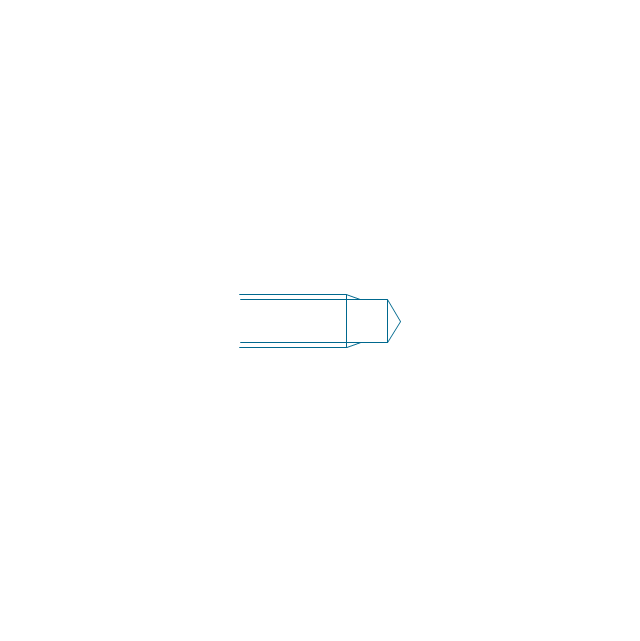
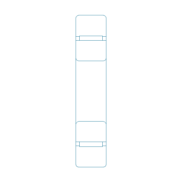
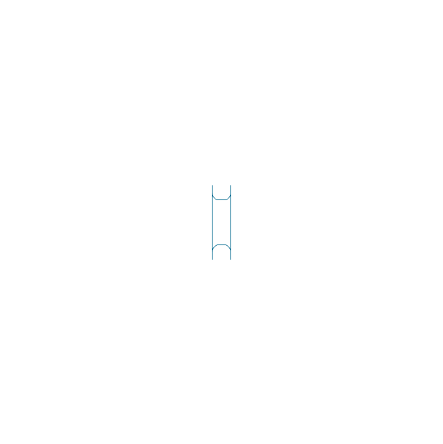
Tapered shaft
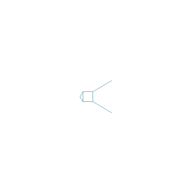
Tapered key

Tapered key (gib head)
-bearings---vector-stencils-library.png--diagram-flowchart-example.png)
Tapered shaft

Hole chamfer

Shaft chamfer

Undercut
Centering bore
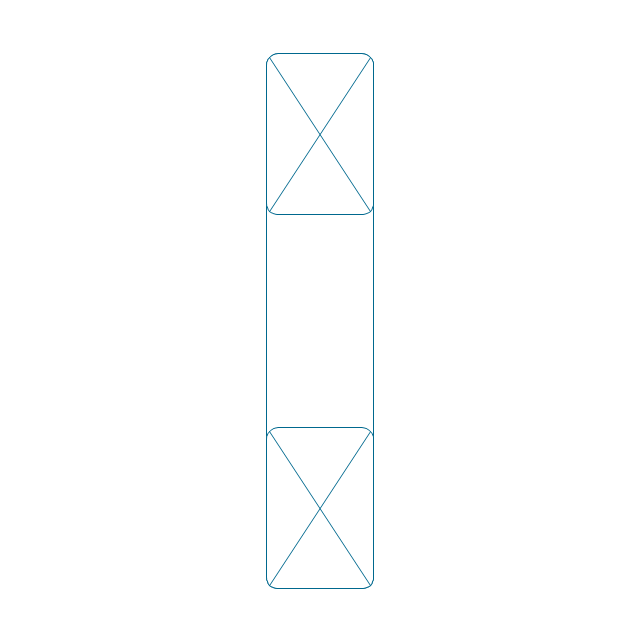
Cutaway

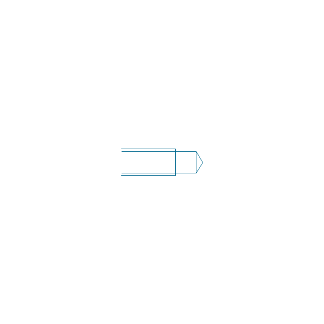
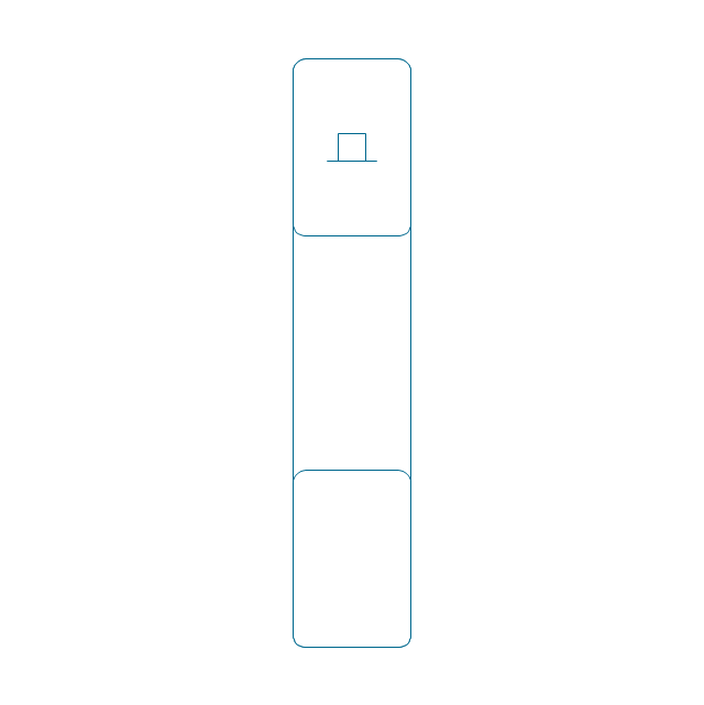
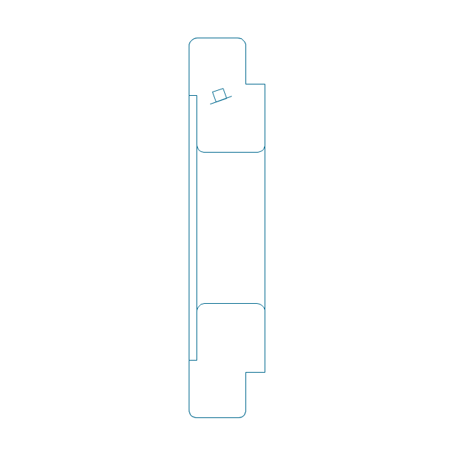
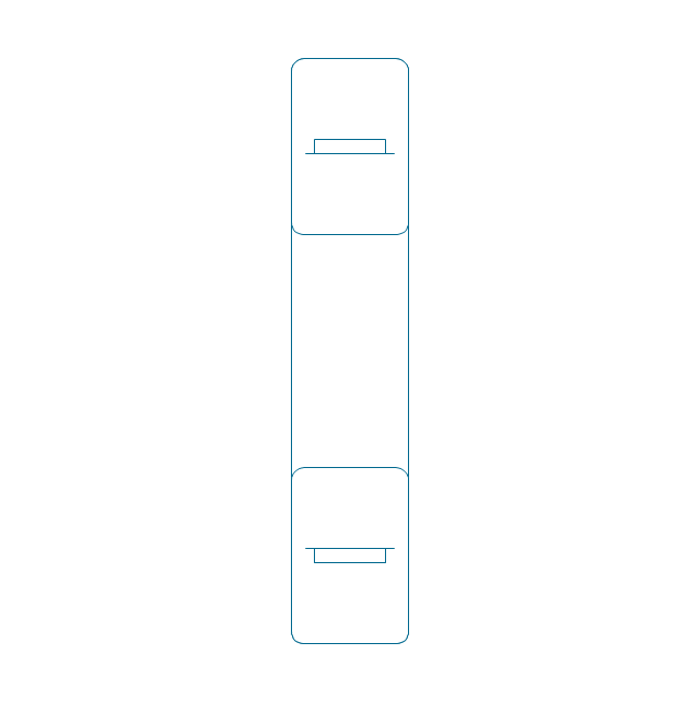
Spindle end

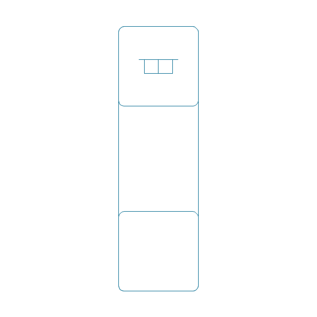
Spindle end (bore)
-bearings---vector-stencils-library.png--diagram-flowchart-example.png)
Countersunk hole

Countersunk hole 2

Threaded hole

Threaded hole 2

The vector stencils library "Bearings" contains 59 symbols of ball bearings, roller bearings, shafts, springs, gears, hooks, spindles, and keys.
Use it to design engineering drawings of machine tools and mechanical devices.
"A bearing is a machine element that constrains relative motion and reduce friction between moving parts to only the desired motion. The design of the bearing may, for example, provide for free linear movement of the moving part or for free rotation around a fixed axis; or, it may prevent a motion by controlling the vectors of normal forces that bear on the moving parts. Many bearings also facilitate the desired motion as much as possible, such as by minimizing friction. Bearings are classified broadly according to the type of operation, the motions allowed, or to the directions of the loads (forces) applied to the parts." [Bearing (mechanical). Wikipedia]
The shapes example "Design elements - Bearings" was created using the ConceptDraw PRO diagramming and vector drawing software extended with the Mechanical Engineering solution from the Engineering area of ConceptDraw Solution Park.
Bearing symbols

"A hydraulic circuit is a system comprising an interconnected set of discrete components that transport liquid. The purpose of this system may be to control where fluid flows (as in a network of tubes of coolant in a thermodynamic system) or to control fluid pressure (as in hydraulic amplifiers).
... hydraulic circuit theory works best when the elements (passive component such as pipes or transmission lines or active components such as power packs or pumps) are discrete and linear. This usually means that hydraulic circuit analysis works best for long, thin tubes with discrete pumps, as found in chemical process flow systems or microscale devices." [Hydraulic circuit. Wikipedia]
The engineering drawing example "Hydraulic circuits" was redrawn using ConceptDraw PRO diagramming and vector drawing software from the Wikimedia Commons file: Hydraulic circuits.png.
[commons.wikimedia.org/ wiki/ File:Hydraulic_ circuits.png]
This file is licensed under the Creative Commons Attribution-Share Alike 3.0 Unported license.
[creativecommons.org/ licenses/ by-sa/ 3.0/ deed.en]
The engineering drawing example "Hydraulic circuits" is included in the Mechanical Engineering solution from the Engineering area of ConceptDraw Solution Park.
Hydraulic circuit schematic

Create Floor Plans Easily with ConceptDraw DIAGRAM


 Building Plans Area
The Building Plans Area collects solutions for drawing the building and site plans.
 Building Design Package
Architects and building engineers to develop building documentation, floor plans and building blueprints, to help designers depict bright and innovative design solutions, make beautiful design proposals and represent the most daring design ideas, to communicate ideas and concepts that relate to construction and design, explain requirements to a building contractor and builders, record completed work, and make a record of what currently exists.
Building Plans with ConceptDraw DIAGRAM

- Mechanical Drawing Symbols | Mechanical Engineering | Design ...
- Mechanical Drawing Symbols | Building Plans Area | Shafts And ...
- Design elements - Bearings | Bearings - Vector stencils library ...
- Machine Design Examples For Mechanical Engineering Drawing
- Engineering Drawing Shaft With Key And Gear
- Mechanical Drawing Symbols | Basic Diahram Pnumatic Shaft
- Design elements - Bearings | Mechanical Engineering | Bearing In ...
- Mechanical Drawing Symbols | Design elements - Bearings | Create ...
- Mechanical Bearing Symbol On Engineering Drawing
- Mechanical Drawing Symbols | Design elements - Bearings ...
- Shaft Design Is Standard Charts Power Transmission Elements ...
- Mechanical Engineering | Mechanical Drawing Symbols ...
- Mechanical Drawing Symbols | Bearings - Vector stencils library ...
- Technical Drawing Of Machine Tools
- Mechanical Drawing Symbols | Mechanical Design Software ...
- Symbol For Gear Mechanical Engineering Drawing
- Symbols Of Engineering Drawing Mechanical For Design Of Machine
- Technical drawing - Machine parts assembling | Mechanical ...
- Engineering Drawing Of Machine Movement Part
- Technical drawing - Machine parts assembling | Design elements ...