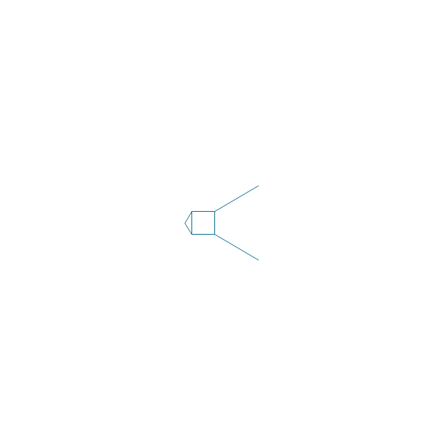
This technical drawing shows the machine parts assembly using joining by threaded fasteners.
"Assembling (joining of the pieces) is done by welding, binding with adhesives, riveting, threaded fasteners, or even yet more bending in the form of a crimped seam. Structural steel and sheet metal are the usual starting materials for fabrication, along with the welding wire, flux, and fasteners that will join the cut pieces. As with other manufacturing processes, both human labor and automation are commonly used. The product resulting from fabrication may be called a fabrication. Shops that specialize in this type of metal work are called fab shops. The end products of other common types of metalworking, such as machining, metal stamping, forging, and casting, may be similar in shape and function, but those processes are not classified as fabrication." [Metal fabrication. Wikipedia]
This mechanical engineering drawing example was designed using ConceptDraw PRO diagramming and vector drawing software extended with Mechanical Engineering solution from Engineering area of ConceptDraw Solution Park.

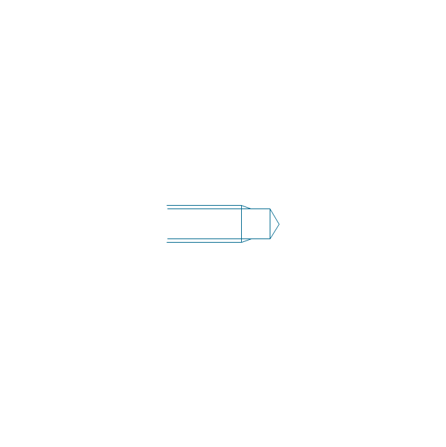
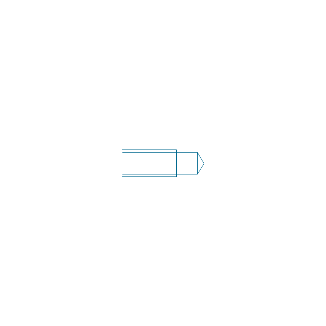
The vector stencils library "Bearings" contains 59 symbols of ball bearings, roller bearings, shafts, springs, gears, hooks, spindles, and keys.
Use it to design engineering drawings of machine tools and mechanical devices.
"A bearing is a machine element that constrains relative motion and reduce friction between moving parts to only the desired motion. The design of the bearing may, for example, provide for free linear movement of the moving part or for free rotation around a fixed axis; or, it may prevent a motion by controlling the vectors of normal forces that bear on the moving parts. Many bearings also facilitate the desired motion as much as possible, such as by minimizing friction. Bearings are classified broadly according to the type of operation, the motions allowed, or to the directions of the loads (forces) applied to the parts." [Bearing (mechanical). Wikipedia]
The shapes example "Design elements - Bearings" was created using the ConceptDraw PRO diagramming and vector drawing software extended with the Mechanical Engineering solution from the Engineering area of ConceptDraw Solution Park.
Bearing symbols

 Engineering
This solution extends ConceptDraw PRO v9.4 with the ability to visualize industrial systems in electronics, electrical, chemical, process, and mechanical engineering.
The vector stencils library "Bearings" contains 59 symbols of ball bearings, roller bearings, shafts, springs, gears, hooks, spindles, and keys.
Use it to design engineering drawings of machine tools and mechanical devices in the ConceptDraw PRO diagramming and vector drawing software extended with the Mechanical Engineering solution from the Engineering area of ConceptDraw Solution Park.
www.conceptdraw.com/ solution-park/ engineering-mechanical
Through hole
Threaded hole 3
Threaded hole 4
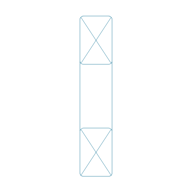
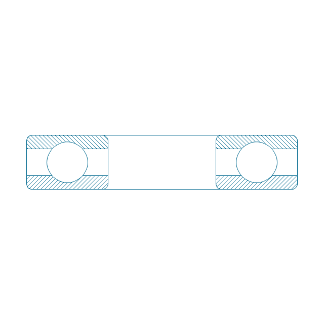
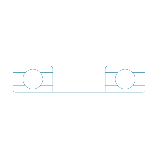
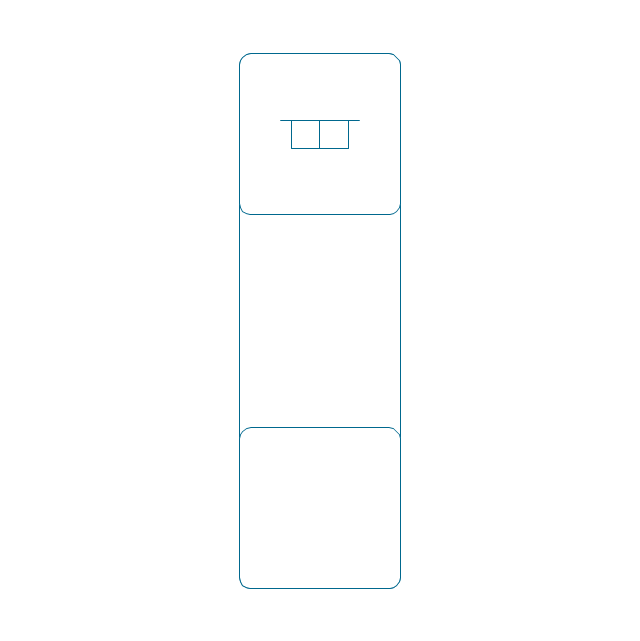
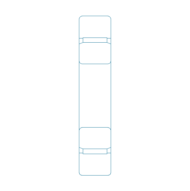
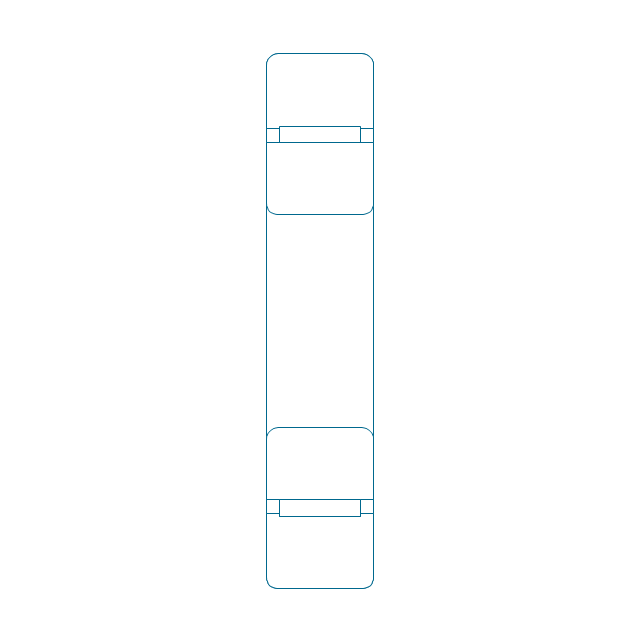
Rolling bearings 2
Rolling bearings
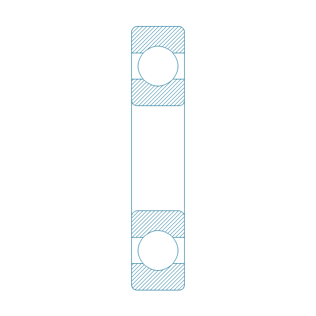
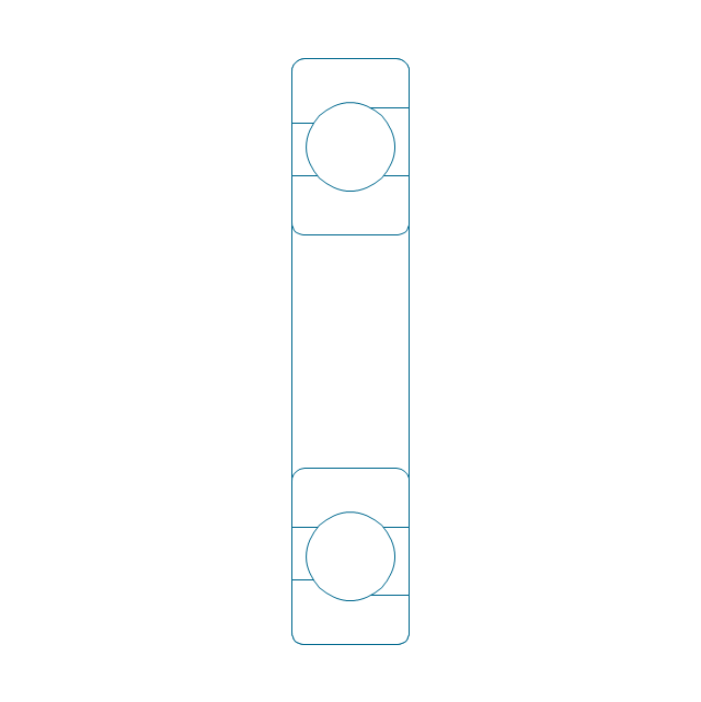
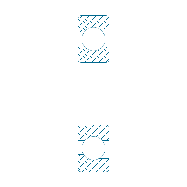
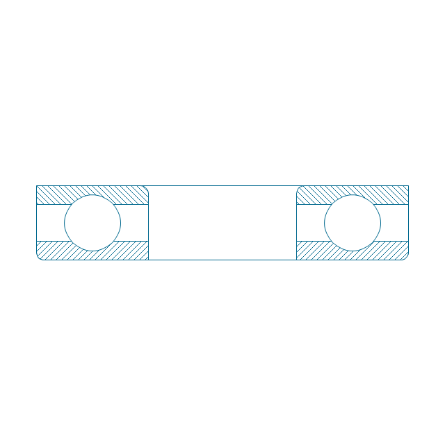
Deep groove ball bearing, hatched
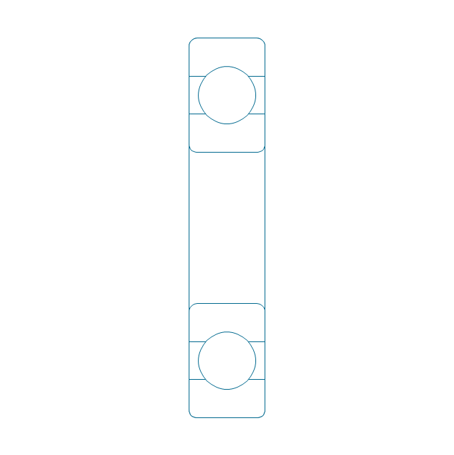
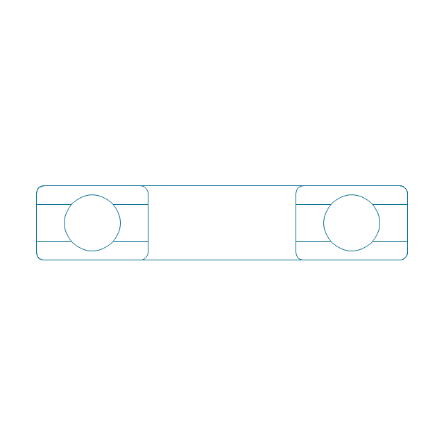
Deep groove ball bearing, unhatched
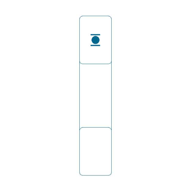
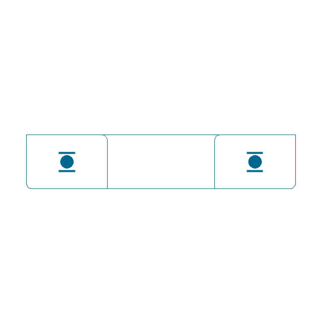
Deep groove ball bearing, simpl.
Angular contact ball bearing, simpl.
Angular contact ball bearing, unhatched
Angular contact ball bearing, hatched
Angular contact ball bearing dbl, unhatched
Angular contact ball bearing dbl, hatched
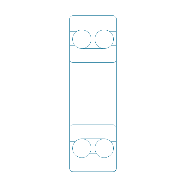
Self align. dbl ball bearing, hatched
Self align. dbl bearing, simpl.
Self align. dbl ball bearing, unhatched
Thrust ball bearing, hatched
Thrust ball bearing, unhatched
Thrust ball bearing, simpl.
Thrust ball bearing, hatched 2
Thrust ball bearing, unhatched 2
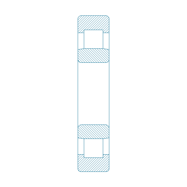
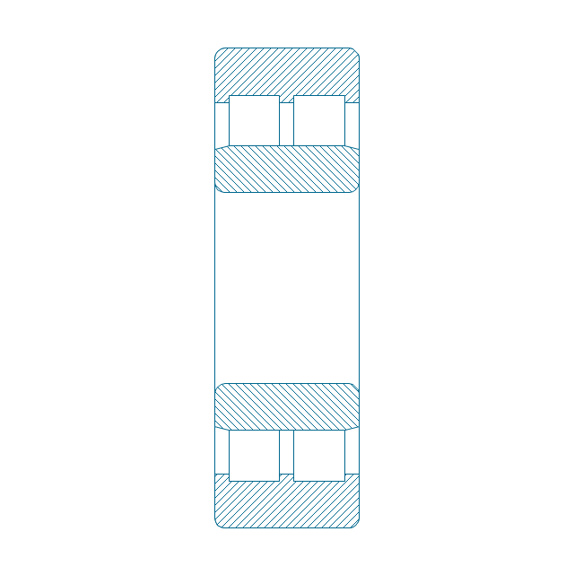
Cylindrical roller bearing, hatched
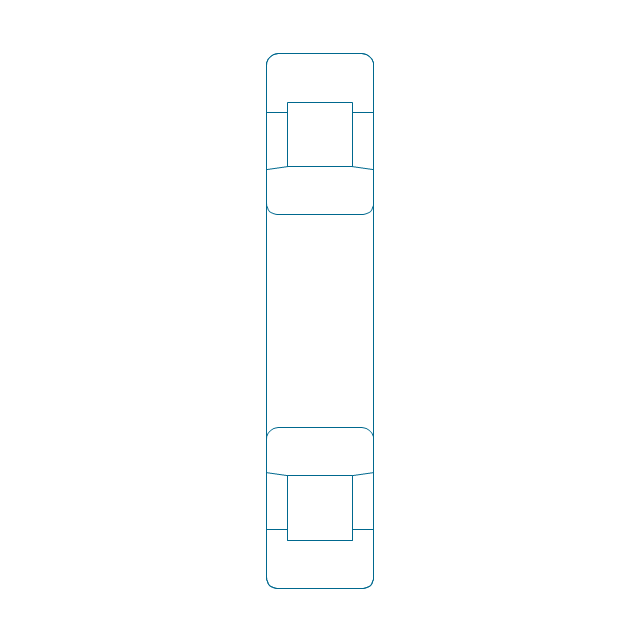
Cylindrical roller bearing, unhatched
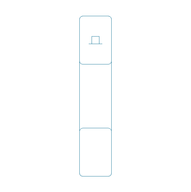
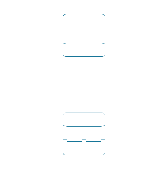
Cylindrical roller bearing, simpl.
Cylindrical roller bearing dbl, simpl.
Cylindrical roller bearing dbl, unhatched
Cylindrical roller bearing dbl, hatched
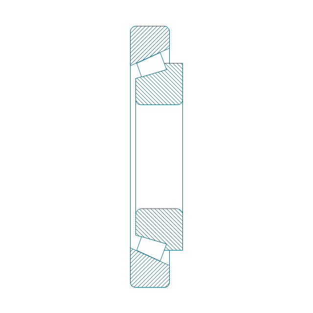
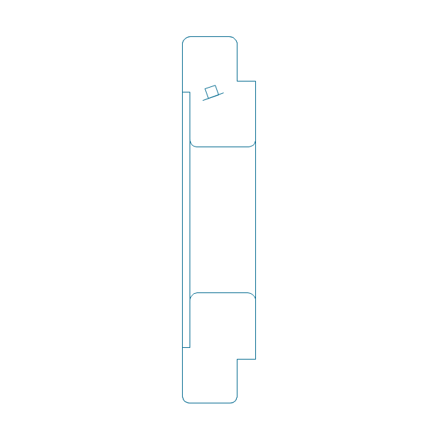
Taper roller bearing, hatched
Taper roller bearing, unhatched
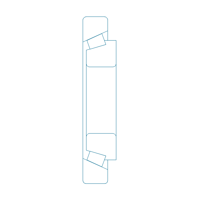
Taper roller bearing, simpl.
Needle roller bearing, hatched
Needle roller bearing, hatched 2
Needle roller bearing, unhatched
Needle roller bearing, unhatched 2
Needle roller bearing, simpl.
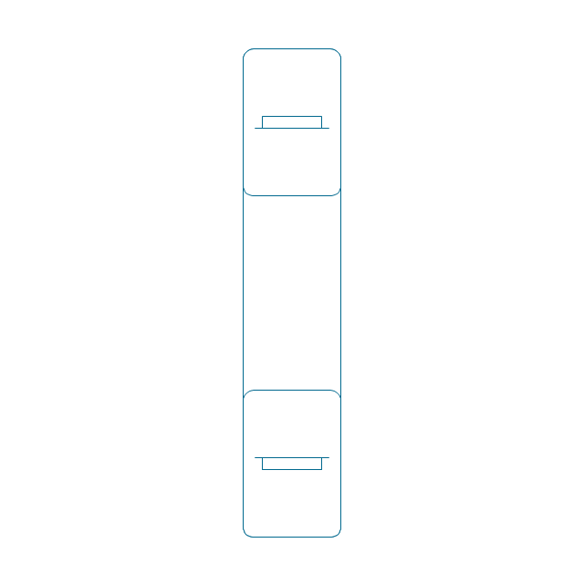
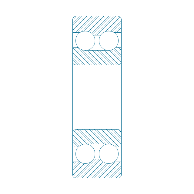
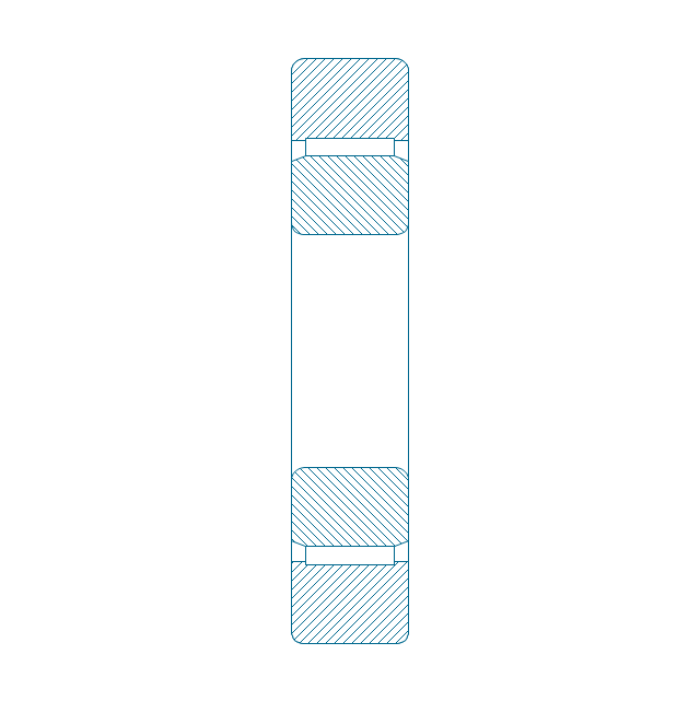
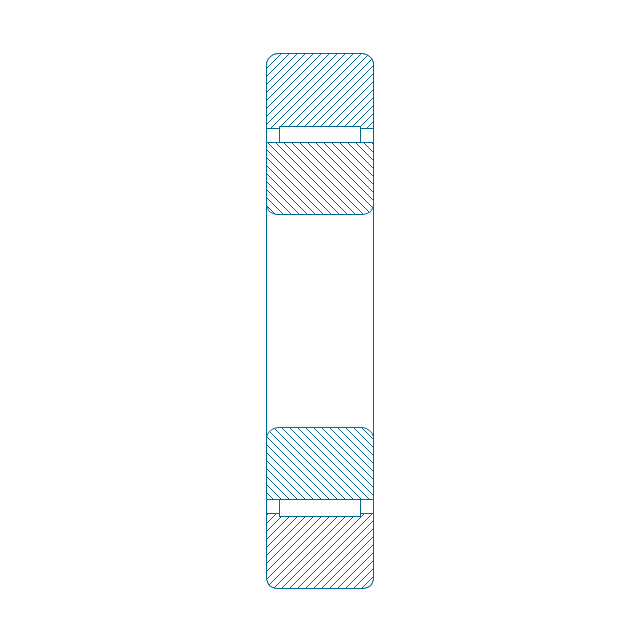
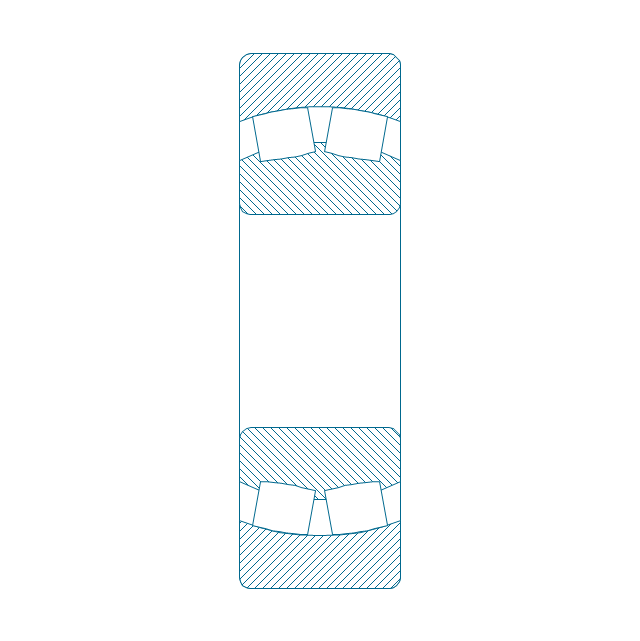
Spher. roller bearing dbl, hatched 2
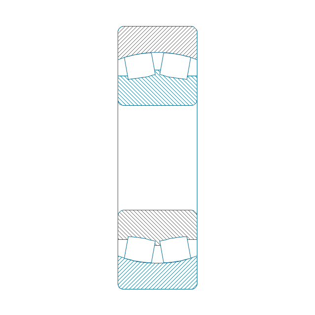
Spher. roller bearing dbl, hatched
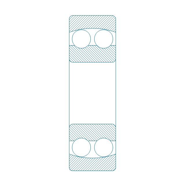
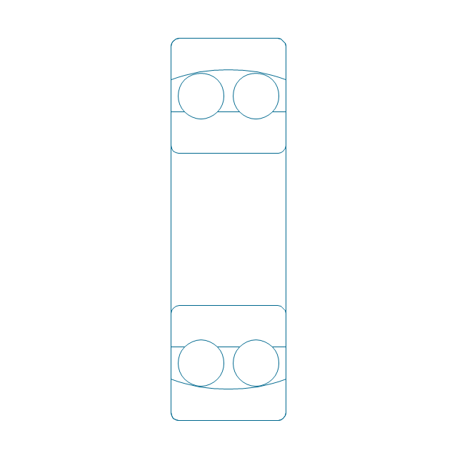
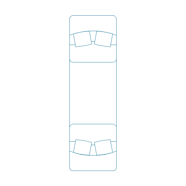
Spher. roller bearing dbl, unhatched
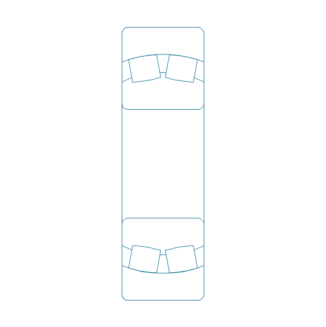
Spher. roller bearing dbl, unhatched 2
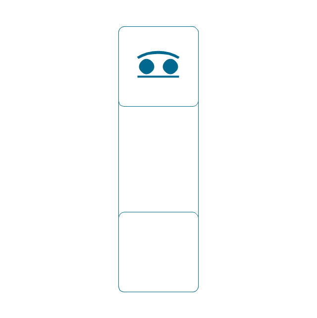
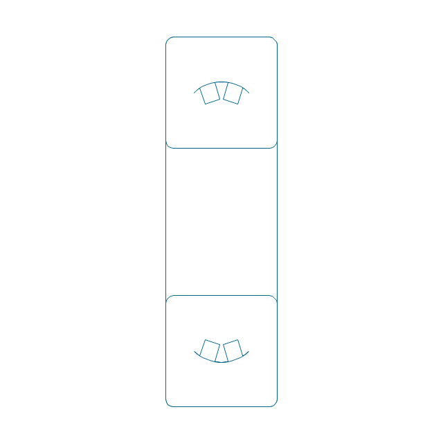
Spher. roller bearing dbl, simpl.
Gear
Gear (web)
-bearings---vector-stencils-library.png--diagram-flowchart-example.png)
Gear (keyway)
-bearings---vector-stencils-library.png--diagram-flowchart-example.png)
Gear (web, keyway)
-bearings---vector-stencils-library.png--diagram-flowchart-example.png)
Tapered shaft
Tapered key

Tapered key (gib head)
-bearings---vector-stencils-library.png--diagram-flowchart-example.png)
Tapered shaft

Hole chamfer
Shaft chamfer

Undercut
Centering bore
Cutaway

Spindle end
Spindle end (bore)
-bearings---vector-stencils-library.png--diagram-flowchart-example.png)
Countersunk hole

Countersunk hole 2

Threaded hole

Threaded hole 2

The vector stencils library "Dimensioning and tolerancing" contains 45 symbols of geometric dimensions and mechanical tolerances, geometric symbols, callouts, and text boxes and inserts.
Use these geometric dimensioning and tolerancing (GD&T) shapes to create annotated mechanical drawings.
"Geometric dimensioning and tolerancing (GD&T) is a system for defining and communicating engineering tolerances. It uses a symbolic language on engineering drawings and computer-generated three-dimensional solid models that explicitly describes nominal geometry and its allowable variation. It tells the manufacturing staff and machines what degree of accuracy and precision is needed on each controlled feature of the part. GD&T is used to define the nominal (theoretically perfect) geometry of parts and assemblies, to define the allowable variation in form and possible size of individual features, and to define the allowable variation between features." [Geometric dimensioning and tolerancing. Wikipedia]
The shapes example "Design elements - Dimensioning and tolerancing" was created using the ConceptDraw PRO diagramming and vector drawing software extended with the Mechanical Engineering solution from the ConceptDraw Solution Park.
Dimensioning and tolerancing symbols

The vector stencils library "Switches and relays" contains 58 symbols of electrical contacts, switches, relays, circuit breakers, selectors, connectors, disconnect devices, switching circuits, current regulators, and thermostats for electrical devices.
"In electrical engineering, a switch is an electrical component that can break an electrical circuit, interrupting the current or diverting it from one conductor to another.
The most familiar form of switch is a manually operated electromechanical device with one or more sets of electrical contacts, which are connected to external circuits. Each set of contacts can be in one of two states: either "closed" meaning the contacts are touching and electricity can flow between them, or "open", meaning the contacts are separated and the switch is nonconducting. The mechanism actuating the transition between these two states (open or closed) can be either a "toggle" (flip switch for continuous "on" or "off") or "momentary" (push-for "on" or push-for "off") type.
A switch may be directly manipulated by a human as a control signal to a system, such as a computer keyboard button, or to control power flow in a circuit, such as a light switch. Automatically operated switches can be used to control the motions of machines, for example, to indicate that a garage door has reached its full open position or that a machine tool is in a position to accept another workpiece. Switches may be operated by process variables such as pressure, temperature, flow, current, voltage, and force, acting as sensors in a process and used to automatically control a system. ... A switch that is operated by another electrical circuit is called a relay. Large switches may be remotely operated by a motor drive mechanism. Some switches are used to isolate electric power from a system, providing a visible point of isolation that can be padlocked if necessary to prevent accidental operation of a machine during maintenance, or to prevent electric shock." [Switch. Wikipedia]
"A relay is an electrically operated switch. Many relays use an electromagnet to mechanically operate a switch, but other operating principles are also used, such as solid-state relays. Relays are used where it is necessary to control a circuit by a low-power signal (with complete electrical isolation between control and controlled circuits), or where several circuits must be controlled by one signal. The first relays were used in long distance telegraph circuits as amplifiers: they repeated the signal coming in from one circuit and re-transmitted it on another circuit. Relays were used extensively in telephone exchanges and early computers to perform logical operations.
A type of relay that can handle the high power required to directly control an electric motor or other loads is called a contactor. Solid-state relays control power circuits with no moving parts, instead using a semiconductor device to perform switching. Relays with calibrated operating characteristics and sometimes multiple operating coils are used to protect electrical circuits from overload or faults; in modern electric power systems these functions are performed by digital instruments still called "protective relays"." [Relay. Wikipedia]
The shapes example "Design elements - Switches and relays" was drawn using the ConceptDraw PRO diagramming and vector drawing software extended with the Electrical Engineering solution from the Engineering area of ConceptDraw Solution Park.
Switch and relay symbols

"Directional control valves route the fluid to the desired actuator. They usually consist of a spool inside a cast iron or steel housing. The spool slides to different positions in the housing, and intersecting grooves and channels route the fluid based on the spool's position. The spool has a central (neutral) position maintained with springs; in this position the supply fluid is blocked, or returned to tank. Sliding the spool to one side routes the hydraulic fluid to an actuator and provides a return path from the actuator to tank. When the spool is moved to the opposite direction the supply and return paths are switched. When the spool is allowed to return to neutral (center) position the actuator fluid paths are blocked, locking it in position. Directional control valves are usually designed to be stackable, with one valve for each hydraulic cylinder, and one fluid input supplying all the valves in the stack. Tolerances are very tight in order to handle the high pressure and avoid leaking, spools typically have a clearance with the housing of less than a thousandth of an inch (25 µm). The valve block will be mounted to the machine's frame with a three point pattern to avoid distorting the valve block and jamming the valve's sensitive components. The spool position may be actuated by mechanical levers, hydraulic pilot pressure, or solenoids which push the spool left or right. A seal allows part of the spool to protrude outside the housing, where it is accessible to the actuator. The main valve block is usually a stack of off the shelf directional control valves chosen by flow capacity and performance. Some valves are designed to be proportional (flow rate proportional to valve position), while others may be simply on-off. The control valve is one of the most expensive and sensitive parts of a hydraulic circuit." [Hydraulic machinery. Wikipedia]
The Windows template "Hydraulic 4-ported 3-position valve" for the ConceptDraw PRO diagramming and vector drawing software is included in the Mechanical Engineering solution from the Engineering area of ConceptDraw Solution Park.
www.conceptdraw.com/ solution-park/ engineering-mechanical
The Windows template "Hydraulic 4-ported 3-position valve" for the ConceptDraw PRO diagramming and vector drawing software is included in the Mechanical Engineering solution from the Engineering area of ConceptDraw Solution Park.
www.conceptdraw.com/ solution-park/ engineering-mechanical
Hydraulic directional control valve

- Mechanical Engineering | Technical drawing - Machine parts ...
- Technical drawing - Machine parts assembling | Engineering ...
- Technical drawing - Machine parts assembling | Mechanical ...
- Mechanical Drawing Symbols | Technical drawing - Machine parts ...
- Mechanical Engineering | Technical drawing - Machine parts ...
- Technical drawing - Machine parts assembling | Design elements ...
- Technical drawing - Machine parts assembling | Engineering ...
- Technical drawing - Machine parts assembling | Design elements ...
- Mechanical Drawing Symbols | Technical Drawing Software ...
- Technical drawing - Machine parts assembling | Process Flowchart ...
- Technical drawing - Machine parts assembling | Design elements ...
- Technical drawing - Machine parts assembling | UML Diagram ...
- Bearing In Engineering Drawing Part S
- UML State Machine Diagram.Design Elements | Technical drawing ...
- How To Draw Mechanical Machine Part
- Technical drawing - Machine parts
- Engineering Drawing Of Machine Movement Part
- Technical Drawing For Mechanical Engineering
- Machine Design Examples For Mechanical Engineering Drawing