This technical drawing shows the machine parts assembly using joining by threaded fasteners.
"Assembling (joining of the pieces) is done by welding, binding with adhesives, riveting, threaded fasteners, or even yet more bending in the form of a crimped seam. Structural steel and sheet metal are the usual starting materials for fabrication, along with the welding wire, flux, and fasteners that will join the cut pieces. As with other manufacturing processes, both human labor and automation are commonly used. The product resulting from fabrication may be called a fabrication. Shops that specialize in this type of metal work are called fab shops. The end products of other common types of metalworking, such as machining, metal stamping, forging, and casting, may be similar in shape and function, but those processes are not classified as fabrication." [Metal fabrication. Wikipedia]
This mechanical engineering drawing example was designed using ConceptDraw PRO diagramming and vector drawing software extended with Mechanical Engineering solution from Engineering area of ConceptDraw Solution Park.

 Engineering
This solution extends ConceptDraw PRO v9.4 with the ability to visualize industrial systems in electronics, electrical, chemical, process, and mechanical engineering.
HelpDesk
How to Create a Mechanical Diagram

 Mechanical Engineering
This solution extends ConceptDraw PRO v.9 mechanical drawing software (or later) with samples of mechanical drawing symbols, templates and libraries of design elements, for help when drafting mechanical engineering drawings, or parts, assembly, pneumatic,
The vector stencils library "Bearings" contains 59 symbols of ball bearings, roller bearings, shafts, springs, gears, hooks, spindles, and keys.
Use it to design engineering drawings of machine tools and mechanical devices.
"A bearing is a machine element that constrains relative motion and reduce friction between moving parts to only the desired motion. The design of the bearing may, for example, provide for free linear movement of the moving part or for free rotation around a fixed axis; or, it may prevent a motion by controlling the vectors of normal forces that bear on the moving parts. Many bearings also facilitate the desired motion as much as possible, such as by minimizing friction. Bearings are classified broadly according to the type of operation, the motions allowed, or to the directions of the loads (forces) applied to the parts." [Bearing (mechanical). Wikipedia]
The shapes example "Design elements - Bearings" was created using the ConceptDraw PRO diagramming and vector drawing software extended with the Mechanical Engineering solution from the Engineering area of ConceptDraw Solution Park.
Bearing symbols

The vector stencils library "Dimensioning and tolerancing" contains 45 symbols of geometric dimensions and mechanical tolerances, geometric symbols, callouts, and text boxes and inserts.
Use these geometric dimensioning and tolerancing (GD&T) shapes to create annotated mechanical drawings.
"Geometric dimensioning and tolerancing (GD&T) is a system for defining and communicating engineering tolerances. It uses a symbolic language on engineering drawings and computer-generated three-dimensional solid models that explicitly describes nominal geometry and its allowable variation. It tells the manufacturing staff and machines what degree of accuracy and precision is needed on each controlled feature of the part. GD&T is used to define the nominal (theoretically perfect) geometry of parts and assemblies, to define the allowable variation in form and possible size of individual features, and to define the allowable variation between features." [Geometric dimensioning and tolerancing. Wikipedia]
The shapes example "Design elements - Dimensioning and tolerancing" was created using the ConceptDraw PRO diagramming and vector drawing software extended with the Mechanical Engineering solution from the ConceptDraw Solution Park.
Dimensioning and tolerancing symbols

The vector stencils library "Valve assembly" contains 141 symbols of pressure and flow regulators, flow direction indicators, controls, and symbols to design flow paths of control valves.
Use these valve assembly shapes to design the engineering drawings of hydraulic and pneumatic valve assemblies in fluid power systems.
"Control valves are valves used to control conditions such as flow, pressure, temperature, and liquid level by fully or partially opening or closing in response to signals received from controllers that compare a "setpoint" to a "process variable" whose value is provided by sensors that monitor changes in such conditions.
The opening or closing of control valves is usually done automatically by electrical, hydraulic or pneumatic actuators. Positioners are used to control the opening or closing of the actuator based on electric, or pneumatic signals.
A control valve consists of three main parts in which each part exist in several types and designs: Valve's actuator, Valve's positioner, Valve's body.
" [Control valves. Wikipedia]
The shapes example "" was created using the ConceptDraw PRO diagramming and vector drawing software extended with the Mechanical Engineering solution from the Engineering area of ConceptDraw Solution Park.
Valve assembly symbols

"Hydraulics is a topic in applied science and engineering dealing with the mechanical properties of liquids. At a very basic level hydraulics is the liquid version of pneumatics. Fluid mechanics provides the theoretical foundation for hydraulics, which focuses on the engineering uses of fluid properties. In fluid power, hydraulics is used for the generation, control, and transmission of power by the use of pressurized liquids. Hydraulic topics range through some part of science and most of engineering modules, and cover concepts such as pipe flow, dam design, fluidics and fluid control circuitry, pumps, turbines, hydropower, computational fluid dynamics, flow measurement, river channel behavior and erosion." [Hydraulics. Wikipedia]
This hydraulic schematic example was redrawn using ConceptDraw PRO diagramming and vector drawing software from the Wikimedia Commons file: Skjematikk.GIF.
[commons.wikimedia.org/ wiki/ File:Skjematikk.GIF]
This file is licensed under the Creative Commons Attribution-Share Alike 3.0 Unported license.
[creativecommons.org/ licenses/ by-sa/ 3.0/ deed.en]
The engineering drawing example "Hydraulic schematic" was created using the ConceptDraw PRO diagramming and vector drawing software extended with the Mechanical Engineering solution from the Engineering area of ConceptDraw Solution Park.
Hydraulic schematic example
"Directional control valves route the fluid to the desired actuator. They usually consist of a spool inside a cast iron or steel housing. The spool slides to different positions in the housing, and intersecting grooves and channels route the fluid based on the spool's position. The spool has a central (neutral) position maintained with springs; in this position the supply fluid is blocked, or returned to tank. Sliding the spool to one side routes the hydraulic fluid to an actuator and provides a return path from the actuator to tank. When the spool is moved to the opposite direction the supply and return paths are switched. When the spool is allowed to return to neutral (center) position the actuator fluid paths are blocked, locking it in position. Directional control valves are usually designed to be stackable, with one valve for each hydraulic cylinder, and one fluid input supplying all the valves in the stack. Tolerances are very tight in order to handle the high pressure and avoid leaking, spools typically have a clearance with the housing of less than a thousandth of an inch (25 µm). The valve block will be mounted to the machine's frame with a three point pattern to avoid distorting the valve block and jamming the valve's sensitive components. The spool position may be actuated by mechanical levers, hydraulic pilot pressure, or solenoids which push the spool left or right. A seal allows part of the spool to protrude outside the housing, where it is accessible to the actuator. The main valve block is usually a stack of off the shelf directional control valves chosen by flow capacity and performance. Some valves are designed to be proportional (flow rate proportional to valve position), while others may be simply on-off. The control valve is one of the most expensive and sensitive parts of a hydraulic circuit." [Hydraulic machinery. Wikipedia]
The Windows template "Hydraulic 4-ported 3-position valve" for the ConceptDraw PRO diagramming and vector drawing software is included in the Mechanical Engineering solution from the Engineering area of ConceptDraw Solution Park.
www.conceptdraw.com/ solution-park/ engineering-mechanical
The Windows template "Hydraulic 4-ported 3-position valve" for the ConceptDraw PRO diagramming and vector drawing software is included in the Mechanical Engineering solution from the Engineering area of ConceptDraw Solution Park.
www.conceptdraw.com/ solution-park/ engineering-mechanical
Hydraulic directional control valve

"Directional control valves are one of the most fundamental parts in hydraulic machinery as well and pneumatic machinery. They allow fluid flow into different paths from one or more sources. They usually consist of a spool inside a cylinder which is mechanically or electrically controlled. The movement of the spool restricts or permits the flow, thus it controls the fluid flow. ...
While working with layouts of hydraulic machinery it is cumbersome to draw actual picture of every valve and other components.instead of pictures symbols are used for variety of components in the hydraulic system to highlight the functional aspects. symbol for directional control valve is made of number of square boxes adjacent to each other depending on the number of positions.connections to the valve are shown on these squares by capital letters.usually they are named only in their normal position and not repeated in other positions.actuation system of the valve is also designated in its symbol." [Directional control valve. Wikipedia]
The Mac template "Pneumatic 5-ported 3-position valve" for the ConceptDraw PRO diagramming and vector drawing software is included in the Mechanical Engineering solution from the Engineering area of ConceptDraw Solution Park.
www.conceptdraw.com/ solution-park/ engineering-mechanical
Pneumatic directional control valve

This example engineering drawing showing the hydraulic directional control valve usage with floating motor and pressure compensated pump is redesigned using the ConceptDraw PRO diagramming and vector drawing software from the Wikimedia Commons file: DCV 17.jpg.
[commons.wikimedia.org/ wiki/ File:DCV_ 17.jpg]
This file is licensed under the Creative Commons Attribution-Share Alike 3.0 Unported license.
[creativecommons.org/ licenses/ by-sa/ 3.0/ deed.en]
"Directional control valves are one of the most fundamental parts in hydraulic machinery as well and pneumatic machinery. They allow fluid flow into different paths from one or more sources. They usually consist of a spool inside a cylinder which is mechanically or electrically controlled. The movement of the spool restricts or permits the flow, thus it controls the fluid flow. ...
The spool (sliding type) consists of lands and grooves.The lands block oil flow through the valve body. The grooves allow oil or gas to flow around the spool and through the valve body. There are two fundamental positions of directional control valve namely normal position where valve returns on removal of actuating force and other is working position which is position of a valve when actuating force is applied. There is another class of valves with 3 or more position that can be spring centered with 2 working position and a normal position. ...
Directional control valves can be classified according to:
(1) number of ports;
(2) number of positions;
(3) actuating methods;
(4) type of spool." [Directional control valve. Wikipedia]
The fluid power equipment drawing example "Directional control valve" is included in the Mechanical Engineering solution from the Engineering area of ConceptDraw Solution Park.
Hydraulic equipment schematic

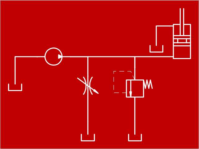
Retract resistor check valve application: pneumatic cylinder, piston driven by Compressed air through 2 Retract resistor check valves.
"A check valve, clack valve, non-return valve or one-way valve is a valve that normally allows fluid (liquid or gas) to flow through it in only one direction.
Check valves are two-port valves, meaning they have two openings in the body, one for fluid to enter and the other for fluid to leave. There are various types of check valves used in a wide variety of applications. Check valves are often part of common household items. Although they are available in a wide range of sizes and costs, check valves generally are very small, simple, or inexpensive. Check valves work automatically and most are not controlled by a person or any external control; accordingly, most do not have any valve handle or stem. The bodies (external shells) of most check valves are made of plastic or metal.
An important concept in check valves is the cracking pressure which is the minimum upstream pressure at which the valve will operate. Typically the check valve is designed for and can therefore be specified for a specific cracking pressure.
Heart valves are essentially inlet and outlet check valves for the heart ventricles, since the ventricles act as pumps." [Check valve. Wikipedia]
This hydraulic schematic example was redrawn using ConceptDraw PRO diagramming and vector drawing software from the Wikimedia Commons file: Retract resistor check valve application.png.
[commons.wikimedia.org/ wiki/ File:Retract_ resistor_ check_ valve_ application.png]
The hydraulic engineering drawing example "Retract resistor check valve application" was created using the ConceptDraw PRO diagramming and vector drawing software extended with the Mechanical Engineering solution from the Engineering area of ConceptDraw Solution Park.
Hydraulic schematic

The vector stencils library "HVAC ductwork" contains 55 ducts, vents and HVAC mechanical components symbols.
Use the design elements library "HVAC ductwork" for drawing the HVAC ductwork system diagrams, heating, ventilation, air conditioning, refrigeration, automated building control and environmental control system layout floor plans.
"Ducts are used in heating, ventilation, and air conditioning (HVAC) to deliver and remove air. These needed airflows include, for example, supply air, return air, and exhaust air. Ducts also deliver, most commonly as part of the supply air, ventilation air. As such, air ducts are one method of ensuring acceptable indoor air quality as well as thermal comfort.
A duct system is often called ductwork. Planning ('laying out'), sizing, optimizing, detailing, and finding the pressure losses through a duct system is called duct design." [Duct (HVAC). Wikipedia]
The shapes library "HVAC ductwork" is included in the HVAC Plans solution from the Building Plans area of ConceptDraw Solution Park.
HVAC ductwork symbols

- Mechanical Engineering | Technical drawing - Machine parts ...
- Directional control valve | Technical drawing - Machine parts ...
- Engineering | Technical drawing - Machine parts assembling ...
- Bearing In Engineering Drawing Part S
- Technical drawing - Machine parts assembling | How to Create a ...
- Mechanical Drawing Symbols | Technical drawing - Machine parts ...
- Mechanical Engineering | Mechanical Drawing Symbols | How to ...
- Technical drawing - Machine parts assembling | Design elements ...
- Technical drawing - Machine parts assembling | Mechanical ...
- Mechanical Part Drawing Symbols
- Design elements - Bearings | Engineering | Mechanical Drawing ...
- Engineering | Mechanical Drawing Symbols | Technical Drawing ...
- Mechanical Drawing Symbols | Technical Drawing Software ...
- Mechanical Drawing Symbols | Mechanical Drawing Software ...
- Mechanical Engineering | Engineering | Technical Drawing Software ...
- Mechanical Engineering | Mechanical Engineering | How to Create ...
- Mechanical Design Symbols Used In Parts Design
- Mechanical Engineering | Mechanical Drawing Symbols | Technical ...
- Welding symbols | Mechanical Engineering | Design elements ...
- Technical drawing - Machine parts assembling | Process Flowchart ...