This sport field plan sample was designed on the base of the Wikipedia file: VolleyballCourt.svg. [en.wikipedia.org/ wiki/ File:VolleyballCourt.svg]
This file is licensed under the Creative Commons Attribution-Share Alike 3.0 Unported license. [creativecommons.org/ licenses/ by-sa/ 3.0/ deed.en]
"Volleyball is a team sport in which two teams of six players are separated by a net. Each team tries to score points by grounding a ball on the other team's court under organized rules. It has been a part of the official program of the Summer Olympic Games since 1964. ...
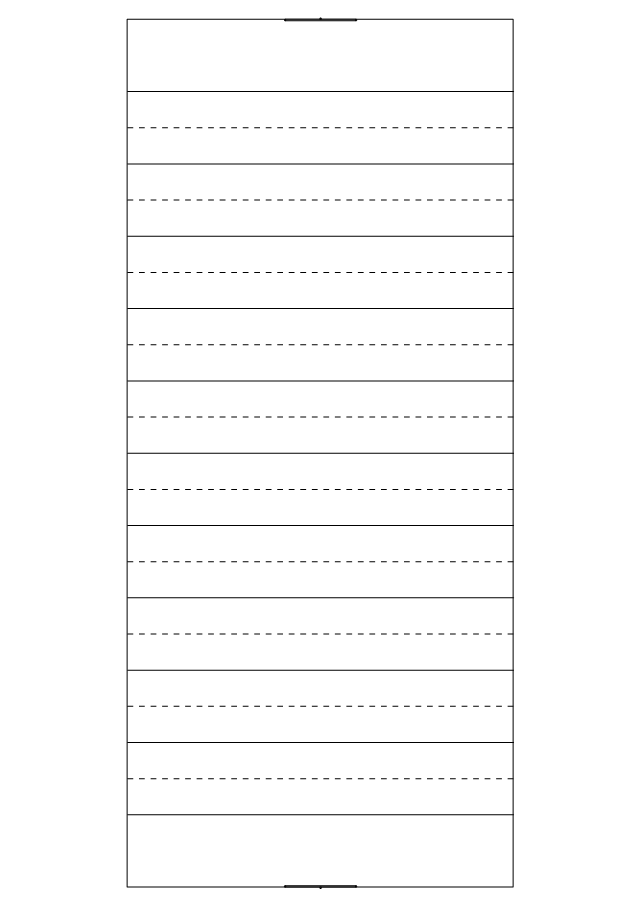
The court dimensions.
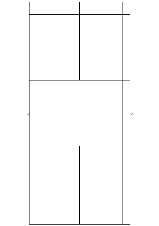
A volleyball court is 18 m (59 ft) long and 9 m (29.5 ft) wide, divided into 9 m × 9 m halves by a one-meter (40-inch) wide net. The top of the net is 2.43 m (8 ft 0 in) above the center of the court for men's competition, and 2.24 m (7 ft 4 in) for women's competition, varied for veterans and junior competitions.
The minimum height clearance for indoor volleyball courts is 7 m (23 ft), although a clearance of 8 m (26 ft) is recommended.
A line 3 m (9.84 ft) from and parallel to the net is considered the "attack line". This "3 meter" (or "10-foot") line divides the court into "back row" and "front row" areas (also back court and front court). These are in turn divided into 3 areas each: these are numbered as follows, starting from area "1", which is the position of the serving player.
After a team gains the serve (also known as siding out), its members must rotate in a clockwise direction, with the player previously in area "2" moving to area "1" and so on, with the player from area "1" moving to area "6".
The team courts are surrounded by an area called the free zone which is a minimum of 3 meters wide and which the players may enter and play within after the service of the ball. All lines denoting the boundaries of the team court and the attack zone are drawn or painted within the dimensions of the area and are therefore a part of the court or zone. If a ball comes in contact with the line, the ball is considered to be "in". An antenna is placed on each side of the net perpendicular to the sideline and is a vertical extension of the side boundary of the court. A ball passing over the net must pass completely between the antennae (or their theoretical extensions to the ceiling) without contacting them." [Volleyball. Wikipedia]
The sport field plan example "Volleyball court dimensions" was created using the ConceptDraw PRO diagramming and vector drawing software extended with the Sport Field Plans solution from the Building Plans area of ConceptDraw Solution Park.
This file is licensed under the Creative Commons Attribution-Share Alike 3.0 Unported license. [creativecommons.org/ licenses/ by-sa/ 3.0/ deed.en]
"Volleyball is a team sport in which two teams of six players are separated by a net. Each team tries to score points by grounding a ball on the other team's court under organized rules. It has been a part of the official program of the Summer Olympic Games since 1964. ...
The court dimensions.
A volleyball court is 18 m (59 ft) long and 9 m (29.5 ft) wide, divided into 9 m × 9 m halves by a one-meter (40-inch) wide net. The top of the net is 2.43 m (8 ft 0 in) above the center of the court for men's competition, and 2.24 m (7 ft 4 in) for women's competition, varied for veterans and junior competitions.
The minimum height clearance for indoor volleyball courts is 7 m (23 ft), although a clearance of 8 m (26 ft) is recommended.
A line 3 m (9.84 ft) from and parallel to the net is considered the "attack line". This "3 meter" (or "10-foot") line divides the court into "back row" and "front row" areas (also back court and front court). These are in turn divided into 3 areas each: these are numbered as follows, starting from area "1", which is the position of the serving player.
After a team gains the serve (also known as siding out), its members must rotate in a clockwise direction, with the player previously in area "2" moving to area "1" and so on, with the player from area "1" moving to area "6".
The team courts are surrounded by an area called the free zone which is a minimum of 3 meters wide and which the players may enter and play within after the service of the ball. All lines denoting the boundaries of the team court and the attack zone are drawn or painted within the dimensions of the area and are therefore a part of the court or zone. If a ball comes in contact with the line, the ball is considered to be "in". An antenna is placed on each side of the net perpendicular to the sideline and is a vertical extension of the side boundary of the court. A ball passing over the net must pass completely between the antennae (or their theoretical extensions to the ceiling) without contacting them." [Volleyball. Wikipedia]
The sport field plan example "Volleyball court dimensions" was created using the ConceptDraw PRO diagramming and vector drawing software extended with the Sport Field Plans solution from the Building Plans area of ConceptDraw Solution Park.
Sport field plan

 Sport Field Plans
Sport Field Plans solution extends ConceptDraw DIAGRAM with samples, templates and libraries of ready-made design elements for developing layouts of sport fields, recreation areas, playground layouts plans, and for professional drawing various sport field plans — for football, basketball, volleyball, golf, baseball, tennis, etc. Depict all your playground layout ideas easily and decisively implement the playground layout designs. Use the final colorful, strict and accurate ConceptDraw's playground layouts when designing the building documentation, brochures, booklets, advertising materials, sports editions, sport maps, business plans, on web sites of sport complexes, sport centers, hotels, etc.
The vector stencils library "Sport fields and recreation" contains 25 shapes of sport fields and recreation design elements. Use it for drawing sport fields and recreation area plans with the ConceptDraw PRO diagramming and vector drawing software.
The vector stencils library "Sport fields and recreation" is included in the Sport Field Plans solution from the Building Plans area of ConceptDraw Solution Park.
The vector stencils library "Sport fields and recreation" is included in the Sport Field Plans solution from the Building Plans area of ConceptDraw Solution Park.
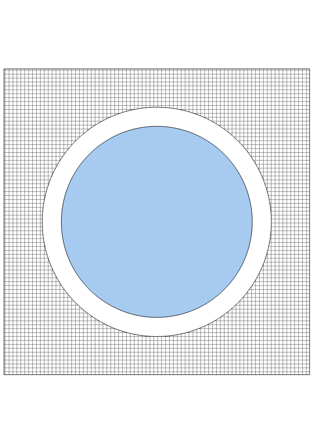
Rectangular pool
Oval pool
Kidney-shaped pool
Lap pool
Competition pool
Spa
Diving board
Swing set
Play structure
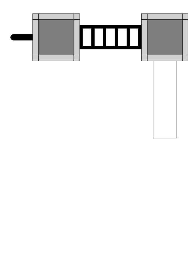
Basketball hoop
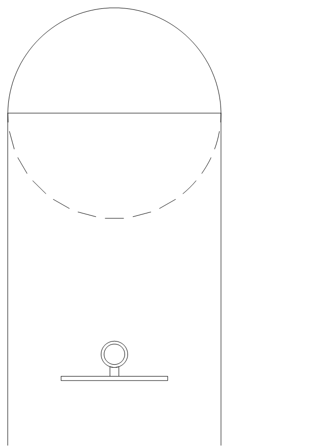
Basketball key
Basketball 3-pt.

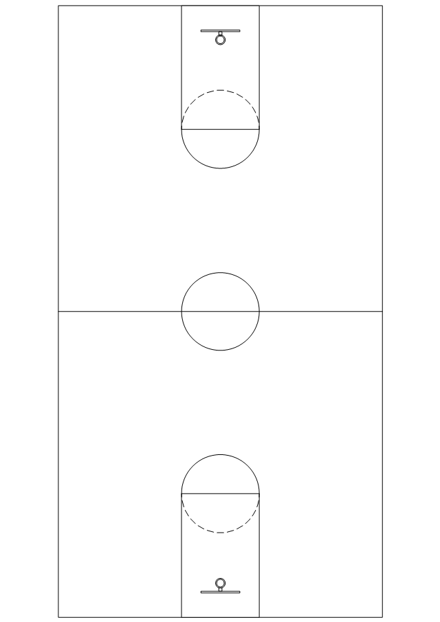
Basketball court
Badminton court
Volleyball court
Tennis court
Soccer field
Football field
Baseball diamonds
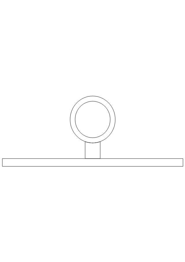
Basketball ring
Barbecue
Swing 1
Swing 2
Sand-box 1
Sand-box 2
This pitch plan sample was designed on the base of the Wikipedia file: Comparison sport playing areas.svg.
[en.wikipedia.org/ wiki/ File:Comparison_ sport_ playing_ areas.svg]
This file is licensed under the Creative Commons Attribution-Share Alike 3.0 Unported license. [creativecommons.org/ licenses/ by-sa/ 3.0/ deed.en]
"A pitch is an outdoor playing area for various sports. The term is used in British and Australian English; the comparable term in American English is playing field. In most sports, the official technical term is field of play, although this is not regularly used by those outside of refereeing/ umpiring circles.
In the sport of cricket, the cricket pitch refers not to the entire field of play, but to the section of the field on which batting and bowling take place in the centre of the field. The pitch is prepared differently to the rest of the field, to provide a harder surface for bowling.
A pitch is often a regulation space, as in an association football pitch." [Pitch (sports field). Wikipedia]
The pitch plan example "Sport fields comparison" was created using the ConceptDraw PRO diagramming and vector drawing software extended with the Sport Field Plans solution from the Building Plans area of ConceptDraw Solution Park.
Pitch plans

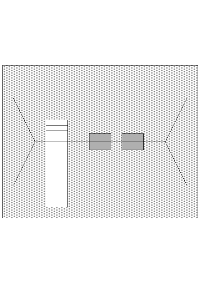
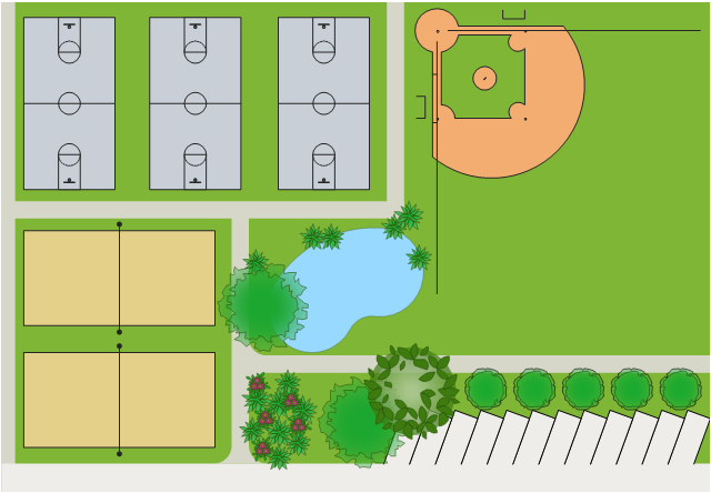
This sports complex plan sample represent the layout of basketball and tennis courts, baseball diamind, swimming pool, trees and parking on the outdoor game playing area.
"A sports complex is a group of sports facilities. For example, there are track and field stadiums, football stadiums, baseball stadiums, swimming pools, and gymnasiums. This area is a sports complex, for fitness." [Sports complex. Wikipedia]
The sports fields layout plan example "Sports complex" was created using the ConceptDraw PRO diagramming and vector drawing software extended with the Sport Field Plans solution from the Building Plans area of ConceptDraw Solution Park.
Pitches site plan
Ice Hockey Rink Dimensions

"A football pitch (also known as a football field or soccer field) is the playing surface for the game of football made of turf. Its dimensions and markings are defined by Law 1 of the Laws of the Game, "The Field of Play".
All line markings on the pitch form part of the area which they define. ...
Pitch boundary.
The pitch is rectangular in shape. The longer sides are called touchlines. The other opposing sides are called the goal lines. ... The two touch lines must also be of the same length... in international matches, the goal lines must be between 64 and 75 m (70 and 80 yd) long and the touchlines must be between 100 and 110 m (110 and 120 yd). All lines must be equally wide, not to exceed 12 centimetres (5 in). The corners of the pitch are demarcated by corner flags. ...
Goals.
Goals are placed at the centre of each goal-line. These consist of two upright posts placed equidistant from the corner flagposts, joined at the top by a horizontal crossbar. The inner edges of the posts must be 7.32 metres (8 yd) apart, and the lower edge of the crossbar must be 2.44 metres (8 ft) above the ground. Nets are usually placed behind the goal, though are not required by the Laws.
Goalposts and crossbars must be white, and made of wood, metal or other approved material." [Association football pitch. Wikipedia]
The diagram example "Association football (soccer) field dimensions" was created using the ConceptDraw PRO diagramming and vector drawing software extended with the Football solution from the Sport area of ConceptDraw Solution Park.
www.conceptdraw.com/ solution-park/ sport-soccer
Association football (soccer) diagram
-diagram-association-football-(soccer)-field-dimensions.png--diagram-flowchart-example.png)
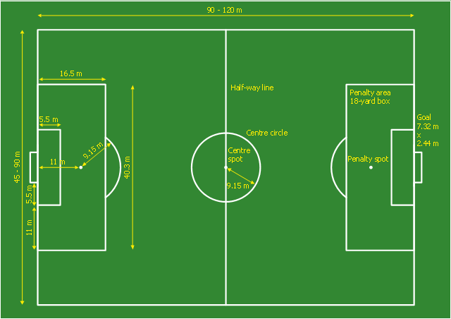
This sport field plan sample was designed on the base of the Wikipedia file: Football pitch metric.svg. [en.wikipedia.org/ wiki/ File:Football_ pitch_ metric.svg]
This file is licensed under the Creative Commons Attribution-Share Alike 3.0 Unported license. [creativecommons.org/ licenses/ by-sa/ 3.0/ deed.en]
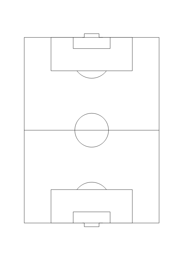
"A football pitch (also known as a football field or soccer field) is the playing surface for the game of football made of turf. Its dimensions and markings are defined by Law 1 of the Laws of the Game, "The Field of Play".
All line markings on the pitch form part of the area which they define. For example, a ball on or above the touchline is still on the field of play; a ball on the line of the goal area is in the goal area; and a foul committed over the 16.5-metre (18-yard) line has occurred in the penalty area. Therefore a ball must completely cross the touchline to be out of play, and a ball must wholly cross the goal line (between the goal posts) before a goal is scored; if any part of the ball is still on or above the line, the ball is still in play." [Association football pitch. Wikipedia]
The sport field plan example "Football pitch metric" was created using the ConceptDraw PRO diagramming and vector drawing software extended with the Sport Field Plans solution from the Building Plans area of ConceptDraw Solution Park.
This file is licensed under the Creative Commons Attribution-Share Alike 3.0 Unported license. [creativecommons.org/ licenses/ by-sa/ 3.0/ deed.en]
"A football pitch (also known as a football field or soccer field) is the playing surface for the game of football made of turf. Its dimensions and markings are defined by Law 1 of the Laws of the Game, "The Field of Play".
All line markings on the pitch form part of the area which they define. For example, a ball on or above the touchline is still on the field of play; a ball on the line of the goal area is in the goal area; and a foul committed over the 16.5-metre (18-yard) line has occurred in the penalty area. Therefore a ball must completely cross the touchline to be out of play, and a ball must wholly cross the goal line (between the goal posts) before a goal is scored; if any part of the ball is still on or above the line, the ball is still in play." [Association football pitch. Wikipedia]
The sport field plan example "Football pitch metric" was created using the ConceptDraw PRO diagramming and vector drawing software extended with the Sport Field Plans solution from the Building Plans area of ConceptDraw Solution Park.
Sport field plan
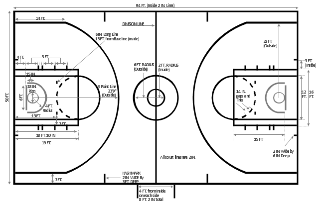
Use this template of American professional basketball court to draw basketball court dimensions diagrams.
The template "Basketball court dimensions" for the ConceptDraw PRO diagramming and vector drawing software is included in the Basketball solution from the Sport area of ConceptDraw Solution Park.
The template "Basketball court dimensions" for the ConceptDraw PRO diagramming and vector drawing software is included in the Basketball solution from the Sport area of ConceptDraw Solution Park.
Basketball court dimensions
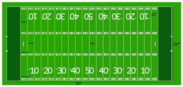
"Football games are played on a rectangular field that measures 120 yards (110 m) long and 53.33 yards (48.76 m) wide. Lines marked along the ends and sides of the field are known respectively as the end lines and side lines, and goal lines are marked 9 yards (8.2 m) outward from each end line. Weighted pylons are placed on the inside corner of the intersections of the goal lines and end lines.
White markings on the field identify the distance from the end zone. Inbound lines, or hash marks, are short parallel lines that mark off 1 yard (0.91 m) increments. Yard lines, which run the width of the field, are marked every 5 yards (4.6 m). A line one yard wide is placed at each end of the field. This line is marked at the center of the two-yard line in professional play and at the three-yard line in college play. Numerals that display the yard lines in multiples of ten are placed along both sides of the field.
Goalposts are at the center of the plane of each of the two end lines. The crossbar of these posts is ten feet (3 meters) above the ground, with vertical uprights at the end of the crossbar 18 feet 6 inches (6 m) apart for professional and collegiate play and 23 feet 4 inches (7 m) apart for high school play. The uprights extend vertically 10 yards on professional fields, a minimum of 10 yards on college fields, and a minimum of ten feet on high school fields. Goal posts are padded at the base, and orange ribbons are normally placed at the tip of each upright." [American football. Wikipedia]
The diagram example "Horizontal colored football field" was created using the ConceptDraw PRO diagramming and vector drawing software extended with the Football solution from the Sport area of ConceptDraw Solution Park.
American football field diagram
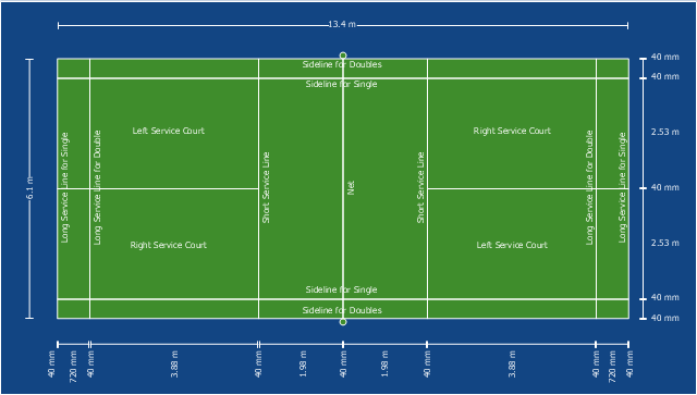
This sport field plan sample depicts the badminton court arena.
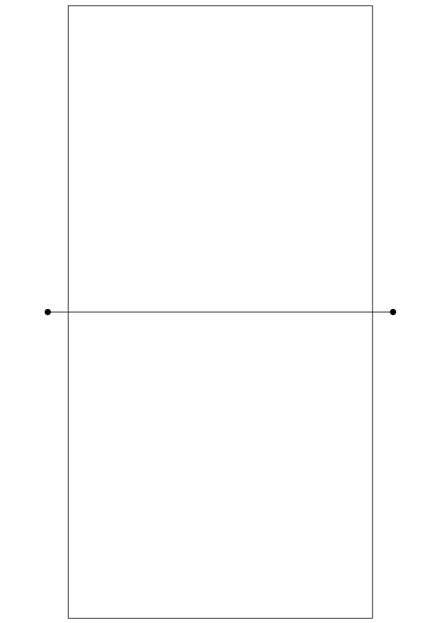
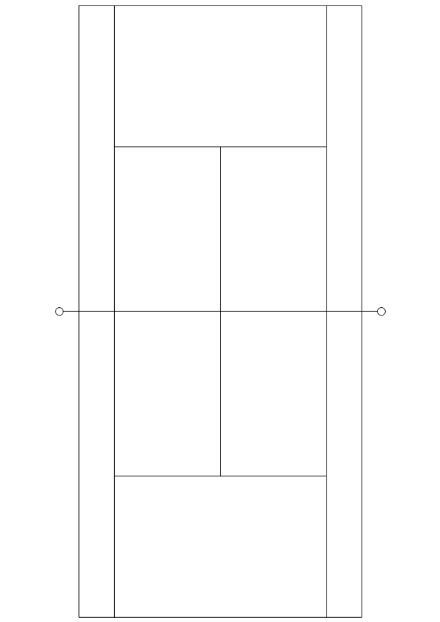
"The court is rectangular and divided into halves by a net. Courts are usually marked for both singles and doubles play, although badminton rules permit a court to be marked for singles only. The doubles court is wider than the singles court, but both are of same length. The exception, which often causes confusion to newer players, is that the doubles court has a shorter serve-length dimension.
The full width of the court is 6.1 metres (20 ft), and in singles this width is reduced to 5.18 metres (17 ft). The full length of the court is 13.4 metres (44 ft). The service courts are marked by a centre line dividing the width of the court, by a short service line at a distance of 1.98 metres (6 ft 6 inch) from the net, and by the outer side and back boundaries. In doubles, the service court is also marked by a long service line, which is 0.76 metres (2 ft 6 inch) from the back boundary.
The net is 1.55 metres (5 ft 1 inch) high at the edges and 1.524 metres (5 ft) high in the centre. The net posts are placed over the doubles sidelines, even when singles is played." [Badminton. Wikipedia]
The sport field plan example "Badminton court" was created using the ConceptDraw PRO diagramming and vector drawing software extended with the Sport Field Plans solution from the Building Plans area of ConceptDraw Solution Park.
Sport field plan
"Markings.
Lines.
The centre line divides the ice in half crosswise. It is used to judge icing, meaning that if a team sends the puck across the centre line (red line), blue line and then across the goal line (that is to say, shoots or dumps the puck past the goal line from behind their own side of the centre line) it is said to be icing. ...
Faceoff spots and circles.
There are 9 faceoff spots on a hockey rink. Most faceoffs take place at these spots. There are two spots in each end zone, two at each end of the neutral zone, and one in the centre of the rink.
There are faceoff circles around the centre ice and end zone faceoff spots. There are hash marks painted on the ice near the end zone faceoff spots. The circles and hash marks show where players may legally position themselves during a faceoff or in game play. ...
Spot and circle dimensions.
Both the center faceoff spot and center faceoff circle are blue. The spot is a solid blue circle 12 inches (30 cm) in diameter. Within the spot is a center, a circle 30 feet (9.1 m) in diameter, painted with a blue line 2 inches (5.1 cm) in width.
All of the other faceoff spots have outlines 2 inches (5.1 cm) thick, forming a circle 2 feet (0.61 m) in diameter measured from the outsides of the outlines, and are filled in with red in all areas except for the 3 inches (7.6 cm) space from the tops and bottoms of the circles, measured from the insides of the outline. ...
Goal posts and nets.
At each end of the ice, there is a goal consisting of a metal goal frame and cloth net in which each team must place the puck to earn points. According to NHL and IIHF rules, the entire puck must cross the entire goal line in order to be counted as a goal. ...
Goal area.
The crease is a special area of the ice designed to allow the goaltender to perform without interference. In most leagues, goals are disallowed if an attacking player enters the goal crease with a stick, skate, or any body part before the puck. For the purposes of this rule, the crease extends vertically from the painted lines to the top of the goal frame. ...
Goaltender trapezoid.
During the 2004-05 American Hockey League (AHL) season, an experimental rule was implemented for the first seven weeks of the season, instituting a goaltender trap zone, more commonly called the trapezoid in reference to its shape. Under the rule, it is prohibited for the goaltender to handle the puck anywhere behind the goal line that is not within the trapezoidal area. If they do so they are assessed a minor penalty for delay of game. ...
Referee's crease.
The referee's crease is a semicircle ten feet in radius in front of the scorekeepers bench." [Ice hockey rink. Wikipedia]
The diagram template "Ice hockey rink view from long side" for the ConceptDraw PRO diagramming and vector drawing software is included in the Hockey solution from the Sport area of ConceptDraw Solution Park.
Ice hockey rink diagram template
How To Draw Building Plans

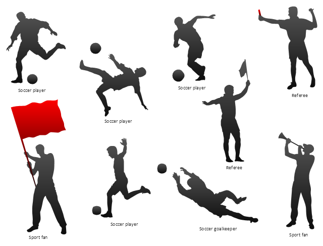
The vector stencils library "Soccer silhouettes" contains 9 association football silhouettes clipart.
"Gameplay.
Association football is played in accordance with a set of rules known as the Laws of the Game. The game is played using a spherical ball (of 71 cm (28 in) circumference in FIFA play), known as the football (or soccer ball). Two teams of eleven players each compete to get the ball into the other team's goal (between the posts and under the bar), thereby scoring a goal. The team that has scored more goals at the end of the game is the winner; if both teams have scored an equal number of goals then the game is a draw. Each team is led by a captain who has only one official responsibility as mandated by the Laws of the Game: to be involved in the coin toss prior to kick-off or penalty kicks.
The primary law is that players other than goalkeepers may not deliberately handle the ball with their hands or arms during play, though they do use their hands during a throw-in restart. Although players usually use their feet to move the ball around, they may use any part of their body (notably, "heading" with the forehead) other than their hands or arms. Within normal play, all players are free to play the ball in any direction and move throughout the pitch, though the ball cannot be received in an offside position." [Association football. Wikipedia]
The clip art example "Design elements - Soccer silhouettes" was created using the ConceptDraw PRO diagramming and vector drawing software extended with the Soccer solution from the Sport area of ConceptDraw Solution Park.
www.conceptdraw.com/ solution-park/ sport-soccer
Silhouettes
"In association football, the formation describes how the players in a team are positioned on the pitch. Different formations can be used depending on whether a team wishes to play more attacking or defensive football. ...
The WM system was created in the mid-1920s by Herbert Chapman of Arsenal to counter a change in the offside law in 1925. The change had reduced the number of opposition players that attackers needed between themselves and the goal-line from three to two. This led to the introduction of a centre-back to stop the opposing centre-forward, and tried to balance defensive and offensive playing. The formation became so successful that by the late-1930s most English clubs had adopted the WM. Retrospectively, the WM has either been described as a 3–2–5 or as a 3–4–3, or more precisely a 3–2–2–3 reflecting the letters which symbolised it. The gap in the centre of the formation between the two wing halves and the two inside forwards allowed Arsenal to counter-attack effectively. The W-M was subsequently adapted by several English sides, but none could apply it in quite the same way Chapman had. This was mainly due to the comparative rarity of Alex James in the English game. He was one of the earliest playmakers in the history of the game, and the hub around which Chapman's Arsenal revolved." [Formation (association football). Wikipedia]
The diagram example "Association football (soccer) formation 3-2-5 (WM)" was created using the ConceptDraw PRO diagramming and vector drawing software extended with the Football solution from the Sport area of ConceptDraw Solution Park.
www.conceptdraw.com/ solution-park/ sport-soccer
Association football (soccer) formation diagram
-formation-diagram-association-football-(soccer)-formation-3-2-5-(wm).png--diagram-flowchart-example.png)
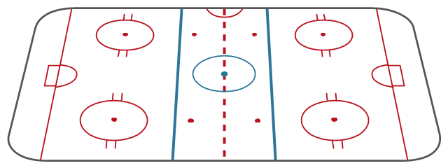
"An ice hockey rink is an ice rink that is specifically designed for ice hockey, a team sport. It is rectangular with rounded corners and surrounded by a wall approximately 1 meter (40-48 inches) high called the boards. ...
There are two standard sizes for hockey rinks: one used primarily in North America, the other used in the rest of the world.
International.
Hockey rinks in most of the world follow the International Ice Hockey Federation (IIHF) specifications, which is 61 metres (200 ft) × 30.5 metres (100 ft) with a corner radius of 8.5 metres (28 ft). The distance from the end boards to the nearest goal line is 4 metres (13 ft). The distance from each goal line to the nearest blue line is 17.3 metres (57 ft). The distance between the two blue lines is also 17.3 metres (57 ft).
North American.
Most North American rinks follow the National Hockey League (NHL) specifications of 200 feet (61 m) × 85 feet (26 m) with a corner radius of 28 feet (8.5 m). The distance from the end boards to the nearest goal line is 11 feet (3.4 m). The NHL attacking zones are expanded, with blue lines 64 feet (20 m) from the goal line and 50 feet (15 m) apart." [Ice hockey rink. Wikipedia]
The diagram template "Hockey rink" for the ConceptDraw PRO diagramming and vector drawing software is included in the Hockey solution from the Sport area of ConceptDraw Solution Park.
Ice hockey rink diagram template

- Volleyball court dimensions | Volleyball Ground Measurement Wiki
- Measurement Of Volleyball Court In Meters Pdf
- Volleyball court dimensions | How To Draw Building Plans | Vally ...
- Volleyball court dimensions | Design elements - Soccer silhouettes ...
- How To Draw Building Plans | Measurement Of Volleyball Ground ...
- Volleyball court dimensions | Sport Field Plans | Basketball | Sports ...
- Volleyball court dimensions | Sport Field Plans | How to Create a ...
- Volleyball court dimensions | How to Create a Sport Field Plan ...
- Volleyball Court Hd Images With Measurement
- Volleyball Court Labels And Measurements
- Volleyball court dimensions | Sport Field Plans | Sport fields ...
- Www Volleyball Court Measurement Pdf
- Volleyball court dimensions | Sport Field Plans | Sport fields ...
- Sport Field Plans | 2017 Volleyball Court Dimensions In Meters Pdf
- Volleyball court dimensions | Sport Field Plans | Design a Soccer ...
- Volleyball Measurements In Metres
- Volleyball court dimensions | Association football (soccer) field ...
- Sport Field Plans | Volleyball court dimensions | Association football ...
- Volleyball court dimensions | Sport Field Plans | Playground Layouts ...
- Label A Volleyball Court