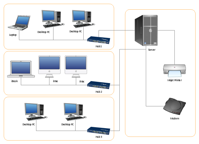
"Physical topology refers to the placement of the network's various components, including device location and cable installation...
The shape of the cabling layout used to link devices is called the physical topology of the network. This refers to the layout of cabling, the locations of nodes, and the interconnections between the nodes and the cabling. The physical topology of a network is determined by the capabilities of the network access devices and media, the level of control or fault tolerance desired, and the cost associated with cabling or telecommunications circuits." [Network topology. Wikipedia]
This physical LAN diagram example was created using the ConceptDraw PRO diagramming and vector drawing software extended with the Computer and Networks solution from the Computer and Networks area of ConceptDraw Solution Park.
Used Solutions
Using Remote Networking Diagrams
Remote Networking - We explain the method most people use to connect to the Internet.
Network Diagramming with ConceptDraw PRO
At the moment computer networks are widespread, various types of computer networks are constructed around the world, operate and interact with each other. There are many kinds of computer networks that differ in the transmission medium, in communications protocols, in size, topology, organizational intent, and also in territorial basis. There are popular such types of computer networks as Global Area Network (GAN), Wide Area Network (WAN), Metropolitan Area Network (MAN), Local Area Network (LAN). ConceptDraw PRO is a powerful network diagramming software, perfect for software engineers, software designers and software developers who need to draw Computer Network diagrams, designs, schematics, and network maps in no time. The pre-drawn shapes representing computers, network devices and smart connectors offered by ConceptDraw solutions help to create the accurate diagrams and documentation, represent computer network topologies and designs, depict Computer network architectures, logical, physical, cable networks, and vehicular networks.Draw Diagram on Mac
Professional diagramming software for mac helps you create Cause and Effect diagram known as Fishbone diagram or Ishikawa diagram from ConceptDraw Business Solution. You will be offered to use templates, samples or draw your diagram using ConceptDraw Arrows10 Technology- Circuits and Logic Diagram Software | Lan Network Amplifier ...
- Circuits and Logic Diagram Software | Network Diagram Software ...
- Local area network (LAN ). Computer and Network Examples ...
- Diagrams Of Lan Wan Man Networks
- Local area network (LAN ). Computer and Network Examples ...
- Network Diagram Software Physical Network Diagram | Network ...
- Network Diagram Software LAN Network Diagrams & Diagrams for ...
- Wide area network (WAN) topology. Computer and Network Examples
- How To use House Electrical Plan Software | Network Diagram ...
- Circuit Diagram In Networking Simple
- Circuits and Logic Diagram Software | Computer Network . Computer ...
- Process Flowchart | Network Diagram Software LAN Network ...
- Network Diagram Software LAN Network Diagrams & Diagrams for ...
- Schematic Diagram Of Local Area Network
- Network Diagram Software LAN Network Diagrams & Diagrams for ...
- Network Topologies | Network Diagram Software LAN Network ...
- How To use House Electrical Plan Software | Local area network ...
- Home area networks (HAN). Computer and Network Examples ...
- Wireless Network WAN | Network Diagram Software LAN Network ...
- Personal area (PAN) networks . Computer and Network Examples ...


