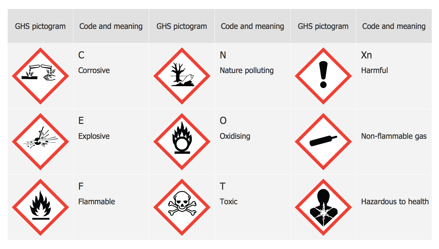
GHS Label Pictograms
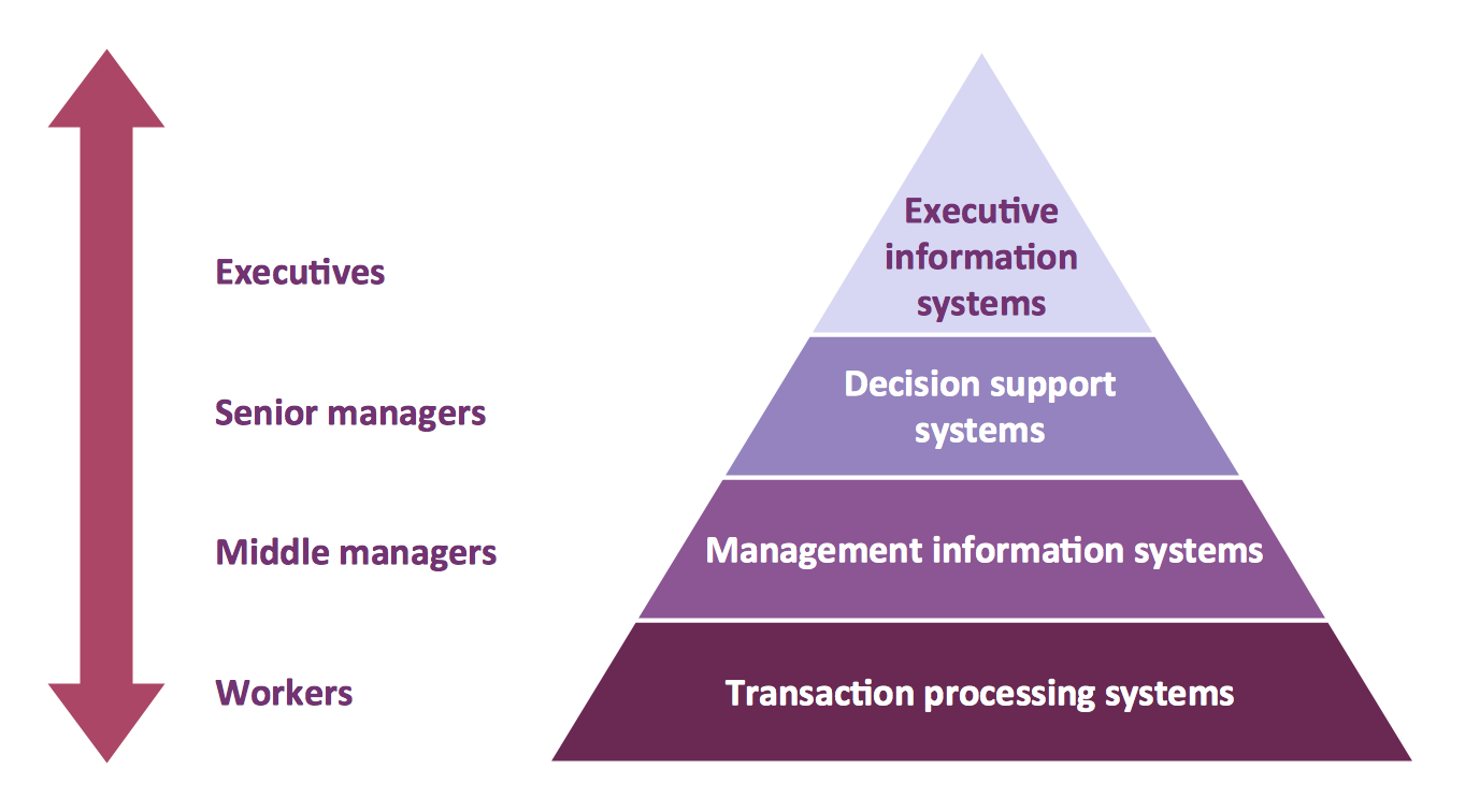
Pyramid Diagram
GHS Labels Meanings
Multiprotocol Label Switching (MPLS). Computer and Network Examples


Local area network (LAN). Computer and Network Examples
 diagram")
Entity Relationship Diagram Symbols

Flow Chart Symbols

This vector stencils library contains 22 symbols of process annotations for setting automatic labels to display a datasheet field for a pipeline shape, labels, captions, outlines, off-sheet labels, text balloons, annotations, outlines, tags, and descriptions.
Use these shapes for drawing Process Flow Diagrams (PFD) and Piping and Instrumentation Diagrams (P&ID) in the ConceptDraw PRO software extended with the Chemical and Process Engineering solution from the Chemical and Process Engineering area of ConceptDraw Solution Park.
www.conceptdraw.com/ solution-park/ engineering-chemical-process
Interface point

Interface point 2 (1st half filled)
-process-annotations---vector-stencils-library.png--diagram-flowchart-example.png)
Interface point 3 (2nd half filled)
-process-annotations---vector-stencils-library.png--diagram-flowchart-example.png)
Interface point 4

Interface point 5 (1st half filled)
-process-annotations---vector-stencils-library.png--diagram-flowchart-example.png)
Interface point 6 (2nd half filled)
-process-annotations---vector-stencils-library.png--diagram-flowchart-example.png)
Slope

Off-sheet label 1

Off-sheet label 2

Off-sheet label 3

Callout 1

Callout 2

Callout 3

Callout 4

Callout 5

Callout 6

8 pt text and line

10 pt text and line

12 pt text and line

12 pt Arial text block

10 pt Arial text block

8 pt Arial text block

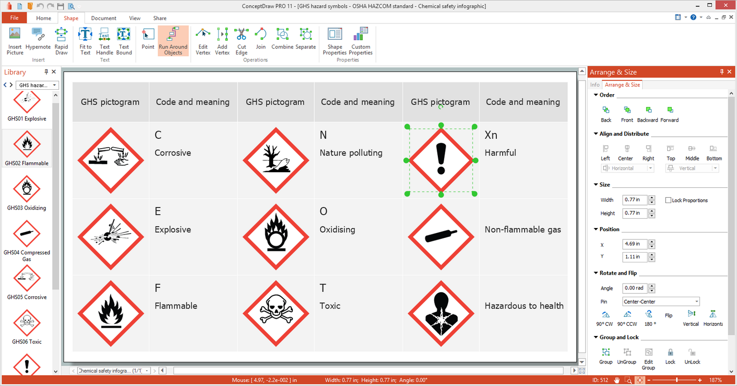
 GHS Hazard Pictograms
GHS Hazard Pictograms solution contains the set of predesigned standard GHS pictograms, Hazardous symbols, and Hazard communication pictograms, approved and agreed by UN in Globally Harmonized System of Classification and Labelling of Chemicals (GHS). They can be used for quick and simple designing accurate and professional-looking infographics, diagrams, warning announcements, signboards, posters, precautionary declarations, regulatory documents, and for representing the main items of OSHA HAZCOM Standard.
- Sample Product Label Design Png
- Label Png Icon
- Aqua Label Png
- Sport Field Plans | Volleyball Court With Label Download In Png
- Text Label Png
- Cloud round icons - Vector stencils library | Multiprotocol Label ...
- Labels Lines Png
- Tooltip Icons Information Windows 10 Png
- Minimize Button Rectangle Down Arrow Png Icon
- Avatar Png