Electrical Symbols, Electrical Diagram Symbols

ERD Symbols and Meanings


Draw Fishbone Diagram on MAC Software

 Landscape & Garden
The Landscape and Gardens solution for ConceptDraw DIAGRAM is the ideal drawing tool when creating landscape plans. Any gardener wondering how to design a garden can find the most effective way with Landscape and Gardens solution.
Mechanical Drawing Symbols

Notation & Symbols for ERD

ER Diagram Styles

Entity Relationship Diagram - ERD - Software for Design Chen ER Diagrams
_Win_Mac.png)
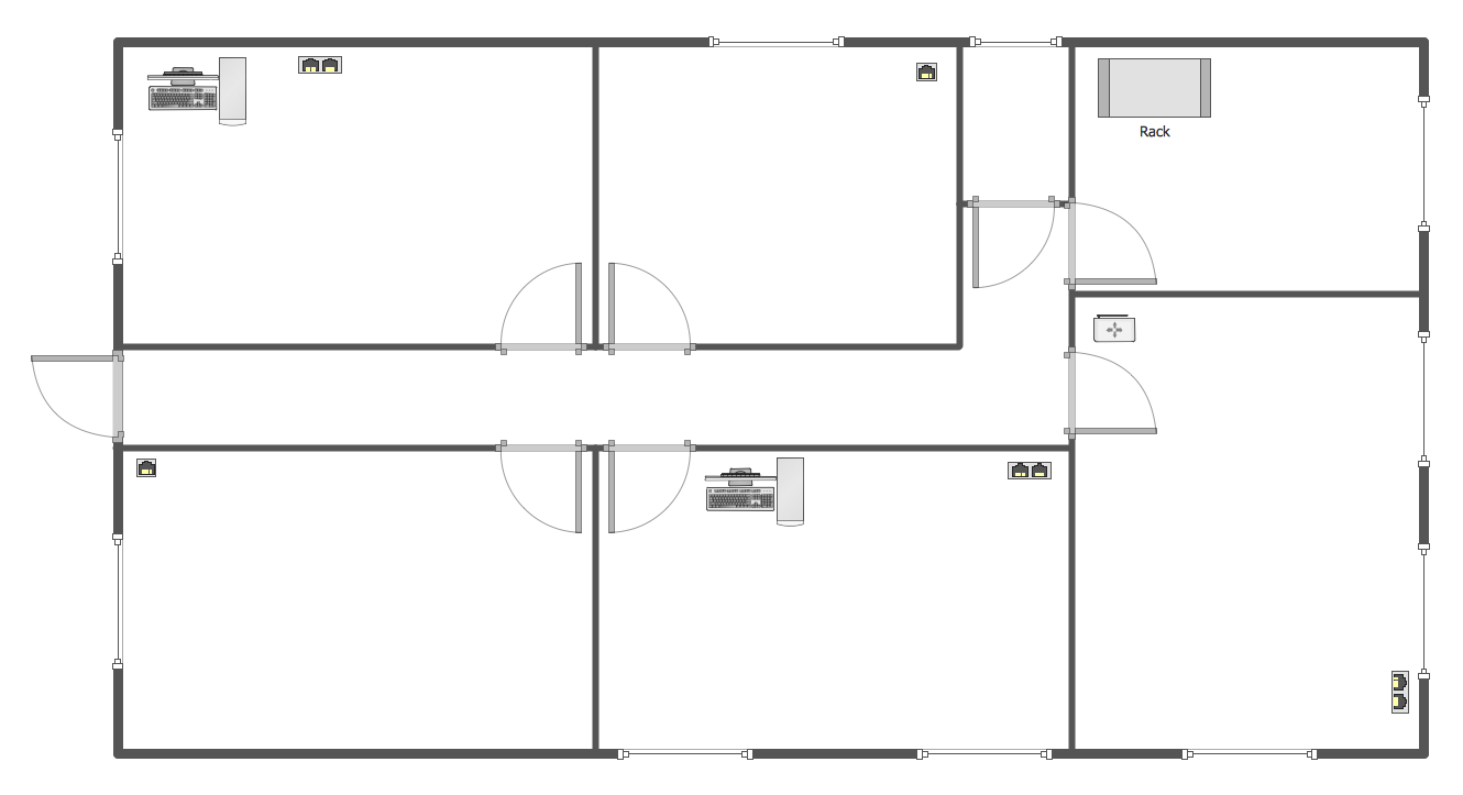
Network Components
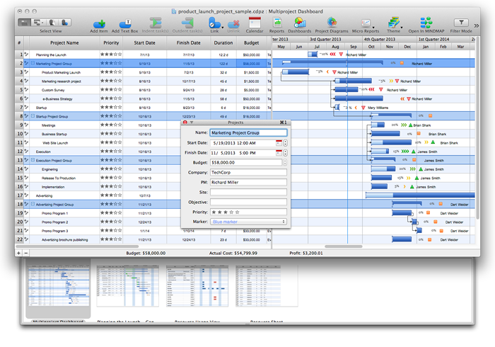
ConceptDraw PROJECT Software Overview
- Identify The Geometrical Shapes Of The Office Furniture Doors And
- What Are The Elements Of Dimensioning
- Arrows - Vector clipart library | Tables - Vector stencils library | Plane ...
- Polygon types | Common joint types | Bubble diagrams in ...
- Polygon types | Common joint types | Bubble diagrams in ...
- Bubble diagrams in Landscape Design with ConceptDraw PRO ...
- Cisco Switches and Hubs. Cisco icons, shapes , stencils and ...
- Design elements - Solid geometry | Design elements - Optics ...
- Software and Database Design with ConceptDraw DIAGRAM | Data ...
- Design In Mechanical Engineering