This reflected ceiling plan sample was created on the base of the article "How to Read a Reflected Ceiling Plan" from wikiHow.com.
"A reflected ceiling plan (RCP) is a drawing, which shows the items that are located on the ceiling of a room or space. It is referred to as a reflected ceiling plan since it is drawn to display a view of the ceiling as if it was reflected onto a mirror on the floor. This way the reflected ceiling plan has the same orientation as the floor plan associated with it. It is as if the ceiling was see-through and you could see right through it to the floor below. Architects and interior designers draw reflected ceiling plans when designing spaces." [wikihow.com/ Read-a-Reflected-Ceiling-Plan]
The HVAC layout example "RCP- HVAC layout" was created using the ConceptDraw DIAGRAM diagramming and vector drawing software extended with the Reflected Ceiling Plans solution from the Building Plans area of ConceptDraw Solution Park.
Reflected ceiling plan

Interior Design. Registers, Drills and Diffusers — Design Elements

 HVAC Plans
Use HVAC Plans solution to create professional, clear and vivid HVAC-systems design plans, which represent effectively your HVAC marketing plan ideas, develop plans for modern ventilation units, central air heaters, to display the refrigeration systems for automated buildings control, environmental control, and energy systems.
This HVAC floor plan sample shows the ventilation duct system layout.
"Ducts are used in heating, ventilation, and air conditioning (HVAC) to deliver and remove air. The needed airflows include, for example, supply air, return air, and exhaust air. Ducts commonly also deliver ventilation air as part of the supply air. As such, air ducts are one method of ensuring acceptable indoor air quality as well as thermal comfort.
A duct system is also called ductwork. Planning (laying out), sizing, optimizing, detailing, and finding the pressure losses through a duct system is called duct design." [Duct (flow). Wikipedia]
The HVAC floor plan example "Ductwork layout" was created using the ConceptDraw DIAGRAM diagramming and vector drawing software extended with the HVAC Plans solution from the Building Plans area of ConceptDraw Solution Park.
HVAC floor plan

HVAC Business Plan
The vector stencil library "HVAC control equipment" contains 81 HVAC control equipment icons.
Use it for drawing HVAC system diagrams, heating, ventilation, air conditioning, refrigeration, automated building control, and environmental control design floor
plans and equipment layouts.
"HVAC (stands for Heating, Ventilation and Air Conditioning) is a control system that applies regulation to a heating and/ or air conditioning system. Usually a sensing device is used to compare the actual state (e.g., temperature) with a target state. Then the control system draws a conclusion what action has to be taken (e.g., start the blower).
More complex HVAC systems can interface to Building Automation System (BAS) to allow the building owners to have more control over the heating or cooling units. The building owner can monitor the system and respond to alarms generated by the system from local or remote locations." [HVAC control system. Wikipedia]
The vector stencils example "Design elements - HVAC control equipment" is included in HVAC Plans solution from the Building Plans area of ConceptDraw Solution
Park.
HVAC control equipment symbols

HVAC Marketing Plan
 Plant Layout Plans
Plant Layout Plans solution can be used for power plant design and plant layout design, for making the needed building plant plans and plant layouts looking professionally good. Having the newest plant layout software, the plant design solutions and in particular the ConceptDraw’s Plant Layout Plans solution, including the pre-made templates, examples of the plant layout plans, and the stencil libraries with the design elements, the architects, electricians, interior designers, builders, telecommunications managers, plant design engineers, and other technicians can use them to create the professionally looking drawings within only a few minutes.
The vector stencil library "HVAC ductwork" contains 63 duct and vent symbols.
Use it for drawing HVAC system diagrams, heating, ventilation, air conditioning, refrigeration, automated building control, and environmental control design floor
plans and equipment layouts.
"Ducts are used in heating, ventilation, and air conditioning (HVAC) to deliver and remove air. These needed airflows include, for example, supply air, return air, and exhaust air. Ducts also deliver, most commonly as part of the supply air, ventilation air. As such, air ducts are one method of ensuring acceptable indoor air quality as well as thermal comfort.
A duct system is often called ductwork. Planning ('laying out'), sizing, optimizing, detailing, and finding the pressure losses through a duct system is called duct design." [Duct (HVAC). Wikipedia]
The vector stencils example "Design elements - HVAC ductwork" is included in HVAC Plans solution from the Building Plans area of ConceptDraw Solution Park.
HVAC ductwork symbols

The vector stencil library "HVAC equipment" contains 84 HVAC equipment symbols as pumps, fans, condensers, pipe coils, silencers, etc.
Use it for drawing HVAC system diagrams, heating, ventilation, air conditioning, refrigeration, automated building control, and environmental control design floor
plans and equipment layouts.
"HVAC (heating, ventilation, and air conditioning) is the technology of indoor and vehicular environmental comfort. HVAC system design is a subdiscipline of mechanical engineering, based on the principles of thermodynamics, fluid mechanics, and heat transfer. Refrigeration is sometimes added to the field's abbreviation as HVAC&R or HVACR, or ventilating is dropped as in HACR (such as the designation of HACR-rated circuit breakers).
HVAC is important in the design of medium to large industrial and office buildings such as skyscrapers and in marine environments such as aquariums, where safe and healthy building conditions are regulated with respect to temperature and humidity, using fresh air from outdoors." [HVAC. Wikipedia]
The vector stencils example "Design elements - HVAC equipment" is included in HVAC Plans solution from the Building Plans area of ConceptDraw Solution Park.
HVAC equipment symbols

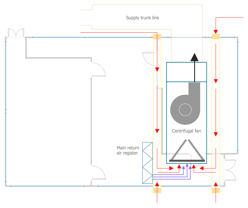
This mechanical room HVAC plan sample shows the layout of air handler (air handling unit, AHU) equipment: mixing chamber, air filter, fan (blower), heat exchanger coil, diffusers.
"Ventilating (the V in HVAC) is the process of "changing" or replacing air in any space to provide high indoor air quality (i.e. to control temperature, replenish oxygen, or remove moisture, odors, smoke, heat, dust, airborne bacteria, and carbon dioxide). Ventilation is used to remove unpleasant smells and excessive moisture, introduce outside air, to keep interior building air circulating, and to prevent stagnation of the interior air.
Ventilation includes both the exchange of air to the outside as well as circulation of air within the building. It is one of the most important factors for maintaining acceptable indoor air quality in buildings. Methods for ventilating a building may be divided into mechanical/ forced and natural types.
"Mechanical" or "forced" ventilation is used to control indoor air quality. Excess humidity, odors, and contaminants can often be controlled via dilution or replacement with outside air. However, in humid climates much energy is required to remove excess moisture from ventilation air.
Ventilation increases the energy needed for heating or cooling, however heat recovery ventilation can be used to mitigate the energy consumption. This involves heat exchange between incoming and outgoing air. Energy recovery ventilation additionally includes exchange of humidity." [Ventilation (architecture). Wikipedia]
The HVAC floor plan example "Ventilation system layout" was created using the ConceptDraw DIAGRAM diagramming and vector drawing software extended with the HVAC Plans solution from the Building Plans area of ConceptDraw Solution Park.
HVAC floor plan

HelpDesk
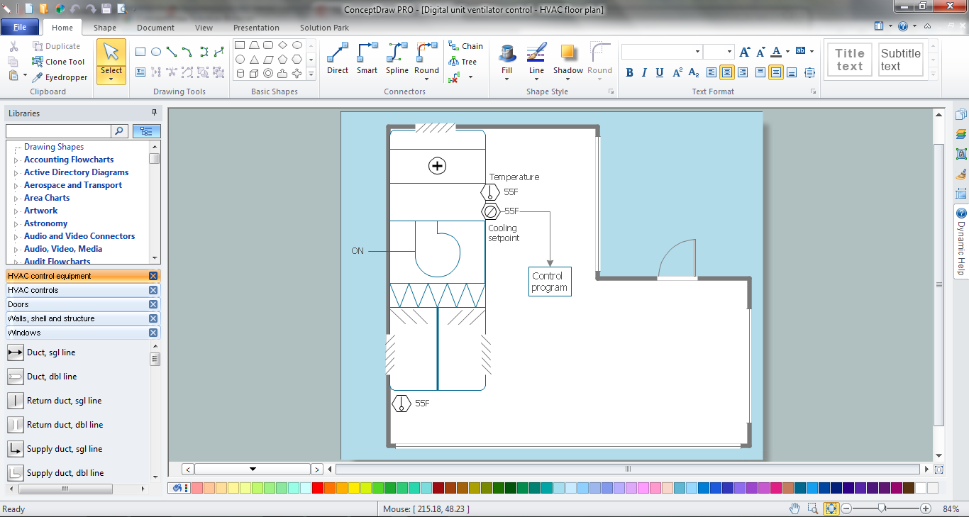
How to Create a HVAC Plan

 Building Design Package
Architects and building engineers to develop building documentation, floor plans and building blueprints, to help designers depict bright and innovative design solutions, make beautiful design proposals and represent the most daring design ideas, to communicate ideas and concepts that relate to construction and design, explain requirements to a building contractor and builders, record completed work, and make a record of what currently exists.
- HVAC Plans | RCP - HVAC layout | How to Create a HVAC Plan ...
- Ventilation system layout | How to Create a HVAC Plan | RCP ...
- HVAC Plans | Office Layout | Interior Design Office Layout Plan ...
- HVAC Plans | How to Create a HVAC Plan | Block diagram ...
- HVAC Plans | How to Create a HVAC Plan | Air handler- HVAC plan ...
- HVAC Plans | Plant Layout Plans | Business diagrams & Org Charts ...
- Design elements - HVAC equipment | Interior Design Office Layout ...
- Design elements - HVAC equipment | Fresh Air Layout Plan
- ATM UML Diagrams | HVAC Marketing Plan | Plant Layout Plans ...
- Design elements - HVAC equipment | Plant Layout Plans | ATM UML ...
- Design elements - HVAC ductwork | Ductwork layout | HVAC ...
- HVAC Business Plan | Office Layout Plans | Small Office Design ...
- Design elements - HVAC ductwork | HVAC Business Plan | HVAC ...
- Ductwork layout | HVAC Plans | Design elements - HVAC ductwork ...
- Office Layout Plans | Office Layout | Small Office Design | Small ...
- Building Drawing Software for Design School Layout | School and ...
- How to Create a HVAC Plan | Building Drawing Software for Design ...
- Design elements - HVAC ductwork | Ductwork layout | Drawing ...
- Design elements - HVAC ductwork | Interior Design Office Layout ...
- Design elements - HVAC ductwork | HVAC ductwork - Vector ...