Mathematics Symbols

Basic Flowchart Symbols and Meaning


Mathematical Diagrams

Flowchart Components

 Mathematics
Mathematics solution extends ConceptDraw PRO software with templates, samples and libraries of vector stencils for drawing the mathematical illustrations, diagrams and charts.
 Object-Role Modeling (ORM) Diagrams
Object-role Modeling (ORM) Diagram solution with powerful vector diagramming and data modeling tools, large quantity of specially developed samples and examples, and rich variety of vector objects corresponding to common ORM notation, ideally suits for developing the comprehensive, clear and visual Object-role Modeling (ORM) diagrams and schematics, understandable for all interested people from the different fields and business directions, for designing the ORM models, and demonstrating advantages from the use of ORM and its notation. It is intended for software developers and computer engineers, specialists in a field of Object-oriented programming (OOP), database architects, web-application constructors and developers, etc.
This engineering drawing shows different types of geometry of butt welds.
"Welds can be geometrically prepared in many different ways. The five basic types of weld joints are the butt joint, lap joint, corner joint, edge joint, and T-joint (a variant of this last is the cruciform joint). Other variations exist as well - for example, double-V preparation joints are characterized by the two pieces of material each tapering to a single center point at one-half their height. Single-U and double-U preparation joints are also fairly common - instead of having straight edges like the single-V and double-V preparation joints, they are curved, forming the shape of a U. Lap joints are also commonly more than two pieces thick - depending on the process used and the thickness of the material, many pieces can be welded together in a lap joint geometry." [Welding. Wikipedia]
This engineering drawing example was redesigned using the ConceptDraw PRO diagramming and vector drawing software from the Wikimedia Commons file: Butt Weld Geometry.GIF.
[commons.wikimedia.org/ wiki/ File:Butt_ Weld_ Geometry.GIF]
The engineering drawing example "Butt weld geometry" is included in the Mechanical Engineering solution from the Engineering area of ConceptDraw Solution Park.
Welding joint diagram

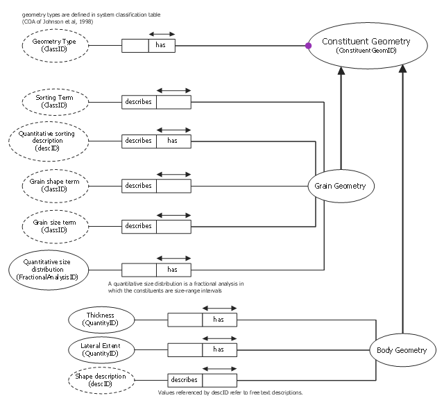
This object-role modeling (ORM) diagram sample shows schema for constituent geometry. It was designed on the base of the Wikimedia Commons file: Schema for Constituent Geometry.gif. [commons.wikimedia.org/ wiki/ File:Schema_ for_ Constituent_ Geometry.gif]
"Constituent Geometry... models a data structure for describing the geometry of individual constituents in a Particular Lithology. These descriptions are based on terms that may have qualitative or quantitative definitions (e.g. round, subround, euhedral, subhedral, fine-grained) or on free text descriptions referenced by "descID'. The Constituent Geometry description has two sub-classes, Grain Geometry and Body Geometry, because different terminology is used when describing individual grains or lithologic components in a mixed rock." [pubs.usgs.gov/ of/ 1999/ of99-386/ richard.html]
The object-role modeling diagram example "Constituent geometry ORM diagram" was designed using ConceptDraw PRO software extended with ORM Diagrams solution from Software Development area of ConceptDraw PRO Solution Park.
Object-role model
Scientific Symbols Chart

Mathematics Solution from the Science and Education area of ConceptDraw Solution Park includes a few shape libraries of plane, solid geometric figures, trigonometrical functions and greek letters to help you create different professional looking mathematic illustrations for science and education.
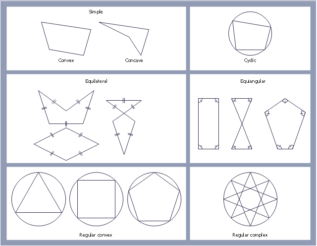
"In geometry a polygon is traditionally a plane figure that is bounded by a finite chain of straight line segments closing in a loop to form a closed chain or circuit. These segments are called its edges or sides, and the points where two edges meet are the polygon's vertices (singular: vertex) or corners. The interior of the polygon is sometimes called its body. An n-gon is a polygon with n sides. A polygon is a 2-dimensional example of the more general polytope in any number of dimensions. ...
The basic geometrical notion has been adapted in various ways to suit particular purposes. Mathematicians are often concerned only with the bounding closed polygonal chain and with simple polygons which do not self-intersect, and they often define a polygon accordingly. A polygonal boundary may be allowed to intersect itself, creating star polygons. Geometrically two edges meeting at a corner are required to form an angle that is not straight (180°); otherwise, the line segments may be considered parts of a single edge; however mathematically, such corners may sometimes be allowed. These and other generalizations of polygons are described below." [Polygon. Wikipedia]
The geometry diagram example "Polygon types" was created using the ConceptDraw PRO diagramming and vector drawing software extended with the Mathematics solution from the Science and Education area of ConceptDraw Solution Park.
Polygon types
- Types Of Polygon With Diagram
- Geometry Diagrams
- Types Of Geometric Diagrams
- Types Of Geometry Diagrams
- Types Of Joint In Welding With Diagram
- Butt weld geometry | Mechanical Engineering | Types Of Butt Joint ...
- Types Of Cones Geometry
- Butt weld geometry | Plumbing and Piping Plans | Diagram Of The ...
- Butt weld geometry | Welded joints types | Welding symbols | Tee ...
- IDEF9 Standard | Butt weld geometry | Types Of Welding Process ...