Activity on Node Network Diagramming Tool

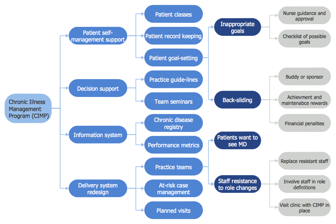
Cause and Effect Analysis
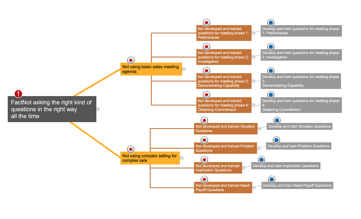

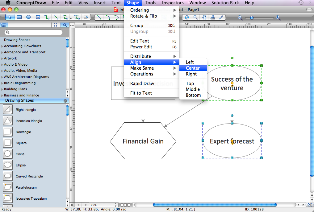
Influence Diagram Software
CORRECTIVE ACTIONS PLANNING. Risk Diagram (PDPC)
Star Network Topology


Program Evaluation and Review Technique (PERT) with ConceptDraw DIAGRAM

 Rapid UML
Rapid UML solution extends ConceptDraw DIAGRAM software with templates, samples and libraries of vector stencils for quick drawing the UML diagrams using Rapid Draw technology.
Cross-Functional Flowchart


 ATM UML Diagrams
The ATM UML Diagrams solution lets you create ATM solutions and UML examples. Use ConceptDraw DIAGRAM as a UML diagram creator to visualize a banking system.
- Activity on Node Network Diagramming Tool | Network Analysis ...
- Cpm Software Free Download
- Decision Tree Software Free Mac
- Cause and Effect Analysis | Influence Diagram Software | Decision ...
- Affinity Diagram | Affinity Diagram Software | Affinity Diagram ...
- Free Decision Tree Software Or Template
- UML Activity Diagram | Activity Network Diagram Method | Activity on ...
- Cpm Template Free
- Cause and Effect Analysis | Influence Diagram Software | Decision ...
- How to Use Critical Path Analysis for Scheduling Complex Projects ...