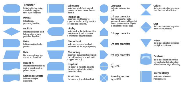
The vector stencils library "Flowchart" contains 26 symbols for drawing the flow charts using the ConceptDraw PRO diagramming and vector drawing software.
"Flowcharts are used in designing and documenting complex processes or programs. Like other types of diagrams, they help visualize what is going on and thereby help the viewer to understand a process, and perhaps also find flaws, bottlenecks, and other less-obvious features within it. There are many different types of flowcharts, and each type has its own repertoire of boxes and notational conventions. The two most common types of boxes in a flowchart are:
(1) a processing step, usually called activity, and denoted as a rectangular box;
(2) a decision, usually denoted as a diamond.
A flowchart is described as "cross-functional" when the page is divided into different swimlanes describing the control of different organizational units. A symbol appearing in a particular "lane" is within the control of that organizational unit. This technique allows the author to locate the responsibility for performing an action or making a decision correctly, showing the responsibility of each organizational unit for different parts of a single process. ...
Common alternate names include: flowchart, process flowchart, functional flowchart, process map, process chart, functional process chart, business process model, process model, process flow diagram, work flow diagram, business flow diagram. The terms "flowchart" and "flow chart" are used interchangeably." [Flowchart. Wikipedia]
The example "Design elements - Flowchart" is included in the Flowcharts solution from the area "What is a Diagram" of ConceptDraw Solution Park.
Flowchart notation
Business Process Modeling Notation Template
 B2B process diagram BPMN 2.0 - Cab booking process")
HelpDesk
How to Create Flowchart Using Standard Flowchart Symbols

HelpDesk
How to Create a Timeline Diagram in ConceptDraw PRO

HelpDesk
How to Create an ERD Diagram
 using Chen's notation")
HelpDesk
How to Create an Audit Flowchart Using ConceptDraw PRO

"Data flow diagrams are one of the three essential perspectives of the structured-systems analysis and design method SSADM. The sponsor of a project and the end users will need to be briefed and consulted throughout all stages of a system's evolution. With a data flow diagram, users are able to visualize how the system will operate, what the system will accomplish, and how the system will be implemented. The old system's dataflow diagrams can be drawn up and compared with the new system's data flow diagrams to draw comparisons to implement a more efficient system. Data flow diagrams can be used to provide the end user with a physical idea of where the data they input ultimately has an effect upon the structure of the whole system from order to dispatch to report. How any system is developed can be determined through a data flow diagram model.
In the course of developing a set of levelled data flow diagrams the analyst/ designers is forced to address how the system may be decomposed into component sub-systems, and to identify the transaction data in the data model.
Data flow diagrams can be used in both Analysis and Design phase of the SDLC.
There are different notations to draw data flow diagrams (Yourdon & Coad and Gane & Sarson), defining different visual representations for processes, data stores, data flow, and external entities." [Data flow diagram. Wikipedia]
The DFD (Yourdon and Coad notation) example "Process of account receivable" was created using the ConceptDraw PRO diagramming and vector drawing software extended with the Data Flow Diagrams solution from the Software Development area of ConceptDraw Solution Park.
Data Flow Diagram

HelpDesk
How to Create a Data Flow Diagram using ConceptDraw PRO
 example")
- Data Flow Diagram Symbols . DFD Library | Basic Flowchart ...
- Swim Lane Diagrams | Cross-Functional Flowchart (Swim Lanes ...
- Business Process Modeling with ConceptDraw | Flow Chart Symbols
- Gane Sarson Diagram | Data Flow Diagram Process | Data flow ...
- Basic Flowchart Symbols and Meaning | How to Draw a Flowchart ...
- Flowchart Symbols Or Design Elements
- Gane Sarson Diagram | Data Flow Diagram Process | Data Flow ...
- Data flow diagram
- UML Class Diagram Example - Medical Shop | UML Notation | Basic ...
- Entity-Relationship Diagram (ERD) | Basic Flowchart Symbols
- DFD (Yourdon and Coad) template | Yourdon and Coad Diagram ...
- Workflow Diagram Symbols | Graphical Symbols to use in EPC ...
- ERD Symbols and Meanings | Entity Relationship Diagram Symbols ...
- Flow chart Example. Warehouse Flowchart | Design elements ...
- Business Process Diagram | Business Process Modeling Notation ...
- ERD Symbols and Meanings | UML Class Diagram Notation ...
- Flowchart notation
- Data Flow Diagram Model
- Basic Flowchart Symbols | Flowchart by Hapman | Design elements ...
- Basic Flowchart Symbols and Meaning | Audit Flowchart Symbols ...