 Fishbone Diagram
Fishbone Diagrams solution extends ConceptDraw PRO software with templates, samples and library of vector stencils for drawing the Ishikawa diagrams for cause and effect analysis.
HelpDesk
How to Create a Fishbone (Ishikawa) Diagram Quickly

 Fishbone Diagrams
The Fishbone Diagrams solution extends ConceptDraw PRO v10 software with the ability to easily draw the Fishbone Diagrams (Ishikawa Diagrams) to clearly see the cause and effect analysis and also problem solving. The vector graphic diagrams produced using this solution can be used in whitepapers, presentations, datasheets, posters, and published technical material.
 Fault Tree Analysis Diagrams
This solution extends ConceptDraw PRO v9.5 or later with templates, fault tree analysis example, samples and a library of vector design elements for drawing FTA diagrams (or negative analytical trees), cause and effect diagrams and fault tree diagrams.
HelpDesk
How To Create a MS Visio Cause and Effect Diagram Using ConceptDraw PRO
 Diagram")
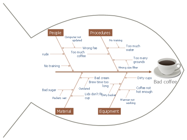
This cause and effect diagram sample was redesigned from the Wikimedia Commons file: Fishbone BadCoffeeExample.jpg. [commons.wikimedia.org/ wiki/ File:Fishbone_ BadCoffeeExample.jpg]
This file is licensed under the Creative Commons Attribution-Share Alike 3.0 Unported license. [creativecommons.org/ licenses/ by-sa/ 3.0/ deed.en]
The fishbone diagram example "Bad coffee" was created using the ConceptDraw PRO diagramming and vector drawing software extended with the Fishbone Diagrams solution from the Management area of ConceptDraw Solution Park.
Fishbone diagram
- Fishbone Diagram | Management | Cisco Network Diagrams ...
- Quality Fish Bone
- What Is A Fish Bone Diagram In Computer Science
- Fish Bone Graph In Science
- Fish Bone Dfd Context Diagram
- Fishbone Diagram | Management | PM Response | Maintenance ...
- Value Stream Mapping | Quality | Fishbone Diagram | Vsm Fish ...
- Fish Bone Diagram
- Fishbone Diagram | Business Productivity Diagramming | Business ...
- Fishbone Diagram | Fishbone Diagrams | How to Create a Fishbone ...
- Images Of Fishbone Diagram
- Fishbone Diagram | Business Productivity Diagramming | How to ...
- Service 8 Ps fishbone diagram - Template | Fishbone Diagram ...
- Business Productivity Diagramming | Business Productivity ...
- Fault Tree Analysis Diagrams | Fishbone Diagram | Structured ...
- Fish Bone Mind Map
- Business Productivity Diagramming | Business Productivity ...
- Fishbone Diagrams | ConceptDraw Solution Park | Biology ...
- How to Create a Fishbone (Ishikawa) Diagram Quickly | Business ...