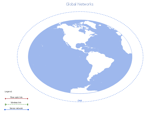
A conceptual diagram of a global vehicular network describes the principles of communication between vehicles, earth-based nodes, and space-based nodes in a wireless network. It illustrates the concept of architecture within global vehicular networks.
"Intelligent transportation systems (ITS) are advanced applications which, without embodying intelligence as such, aim to provide innovative services relating to different modes of transport and traffic management and enable various users to be better informed and make safer, more coordinated, and 'smarter' use of transport networks.
...
Intelligent transport systems vary in technologies applied, from basic management systems such as car navigation; traffic signal control systems; container management systems; variable message signs; automatic number plate recognition or speed cameras to monitor applications, such as security CCTV systems; and to more advanced applications that integrate live data and feedback from a number of other sources, such as parking guidance and information systems; weather information; bridge deicing systems; and the like." [Intelligent transportation system. Wikipedia]
The global vehicular network diagram template is included in the Vehicular Networking solution from the Computer and Networks area of ConceptDraw Solution Park.
Global vehicular network diagram template
The vector stencils library "Cisco optical" contains 19 symbols of optical devices for drawing Cisco computer network diagrams.
"Fiber-optic communication is a method of transmitting information from one place to another by sending pulses of light through an optical fiber. The light forms an electromagnetic carrier wave that is modulated to carry information. ... Because of its advantages over electrical transmission, optical fibers have largely replaced copper wire communications in core networks in the developed world. Optical fiber is used by many telecommunications companies to transmit telephone signals, Internet communication, and cable television signals. ...
The process of communicating using fiber-optics involves the following basic steps: Creating the optical signal involving the use of a transmitter, relaying the signal along the fiber, ensuring that the signal does not become too distorted or weak, receiving the optical signal, and converting it into an electrical signal." [Fiber-optic communication. Wikipedia]
The symbols example "Cisco optical - Vector stencils library" was created using the ConceptDraw PRO diagramming and vector drawing software extended with the Cisco Network Diagrams solution from the Computer and Networks area of ConceptDraw Solution Park.
www.conceptdraw.com/ solution-park/ computer-networks-cisco
Automatic Protection Switching (APS)
-cisco-optical---vector-stencils-library.png--diagram-flowchart-example.png)
Channelized pipe

Concatenated payload

Optical cross-connect

WDM

Optical fiber

ONS 15104

SONET MUX

Optical amplifier

Digitall cross-connect

Optical services router

Cisco 10700

Optical transport

Wide Area Application Engine (WAE)
-cisco-optical---vector-stencils-library.png--diagram-flowchart-example.png)
Protected optical

Unprotected optical

Metro 1500

ONS 15500

Pipe

Network Glossary Definition


Telecommunication networks. Computer and Network Examples

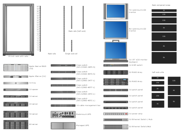
The vector stencils library "Rack diagrams" contains 33 rack design elements for drawing the computer network server rack diagrams.
"A 19-inch rack is a standardized frame or enclosure for mounting multiple equipment modules. Each module has a front panel that is 19 inches (482.6 mm) wide, including edges or ears that protrude on each side which allow the module to be fastened to the rack frame with screws. ...
Equipment designed to be placed in a rack is typically described as rack-mount, rack-mount instrument, a rack mounted system, a rack mount chassis, subrack, rack mountable, or occasionally simply shelf. The height of the electronic modules is also standardized as multiples of 1.75 inches (44.45 mm) or one rack unit or U (less commonly RU). The industry standard rack cabinet is 42U tall. ...
19-inch racks in 2-post or 4-post form hold most equipment in modern data centers, ISP facilities and professionally designed corporate server rooms. They allow for dense hardware configurations without occupying excessive floorspace or requiring shelving." [19-inch rack. Wikipedia]
The clip art example "Rack diagrams - Vector stencils library" was created using the ConceptDraw PRO diagramming and vector drawing software extended with the Rack Diagrams solution from the Computer and Networks area of ConceptDraw Solution Park.
19 inch Rack with Rails

Rack

Rack rails

Rack rails (half-width)
-rack-diagrams---vector-stencils-library.png--diagram-flowchart-example.png)
Single rack rail

Xserve RAID

XServe

1U tray

1U spacer

2U server

1U Ethernet Switch/Hub

2U Ethernet Switch/Hub

1U power strip

1U KVM switch

1U patch panel

Rackmount UPS

Cisco switch (WS-C3560-24PS-S)
-rack-diagrams---vector-stencils-library.png--diagram-flowchart-example.png)
Cisco switch (WS-C3560-48TS-S)
-rack-diagrams---vector-stencils-library.png--diagram-flowchart-example.png)
Cisco switch (WS-C2960-48TT-L)
-rack-diagrams---vector-stencils-library.png--diagram-flowchart-example.png)
Cisco switch (WS-C2960-48TC-L)
-rack-diagrams---vector-stencils-library.png--diagram-flowchart-example.png)
Cisco switch (WS-C2960-24TT-L)
-rack-diagrams---vector-stencils-library.png--diagram-flowchart-example.png)
Cisco switch (WS-C2960-24TC-L)
-rack-diagrams---vector-stencils-library.png--diagram-flowchart-example.png)
7U rackmount LCD monitor

8U rackmount LCD monitor

Fiber optic patch panel (type A)
-rack-diagrams---vector-stencils-library.png--diagram-flowchart-example.png)
Fiber optic patch panel (type B)
-rack-diagrams---vector-stencils-library.png--diagram-flowchart-example.png)
Fiber optic patch panel (type C)
-rack-diagrams---vector-stencils-library.png--diagram-flowchart-example.png)
3U server

2U RAID array

3U RAID array

Managed UPS

1U 19'' LCD monitor keyboard

1U server

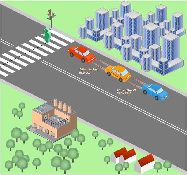
This vehicular network diagram sample was drawn on the base of picture illustrating the post "LED Traffic Signals and Vehicle Lights for Optical Broadband Communications" from the blog "Terranautix".
"Visible Light Communication (VLC) is a rapidly emerging field that focuses on the use of light sources (between 400 THz and 800 THz) for the primary purpose of broadband communications. In order to transmit data over light, the light source (transceiver) is pulsed on and off rapidly to create a data stream, similar to fiber optic communications, but in the wireless form, or “Free-Space Optical Transmission“. By pulsing lights many thousands (and millions) of times per second, data transmission occurs at a rate undetectable by the human eye. Optical receivers convert the light pulses to an electronic signal on the receiver end. The Light Emitting Diode (LED) is the primary form factor currently undergoing extensive research."
[terranautix.com/ tag/ communications]
The vehicular network diagram example "Visible light communication" was created using the ConceptDraw PRO diagramming and vector drawing software extended with the Vehicular Networking solution from the Computer and Networks area of ConceptDraw Solution Park.
Vehicular network diagram
Used Solutions
The vector stencils library "Cisco routers" contains 27 symbols of routers for drawing Cisco computer network diagrams.
"When multiple routers are used in interconnected networks, the routers exchange information about destination addresses using a dynamic routing protocol. Each router builds up a table listing the preferred routes between any two systems on the interconnected networks. A router has interfaces for different physical types of network connections, (such as copper cables, fiber optic, or wireless transmission). It also contains firmware for different networking Communications protocol standards. Each network interface uses this specialized computer software to enable data packets to be forwarded from one protocol transmission system to another.
Routers may also be used to connect two or more logical groups of computer devices known as subnets, each with a different sub-network address. The subnets addresses recorded in the router do not necessarily map directly to the physical interface connections." [Router (computing). Wikipedia]
The symbols example "Cisco routers - Vector stencils library" was created using the ConceptDraw PRO diagramming and vector drawing software extended with the Cisco Network Diagrams solution from the Computer and Networks area of ConceptDraw Solution Park.
www.conceptdraw.com/ solution-park/ computer-networks-cisco
Router

Router, subdued

Router with silicon switch

Wavelength router

NetFlow router

uBR 910

Broadband router

Gigabit switch ATM tag router

ATM tag switch router

ATM router

NetFlow router

Cisco 7505

Cisco 7507

Cisco 7500 ARS (7513)
-cisco-routers---vector-stencils-library.png--diagram-flowchart-example.png)
Voice enabled router

TDM router

IP telephony router

IAD router

Content service router

Cisco storage router

Router with firewall

Wireless router

ASR 1000 series

ATM 3800

AXP

Cable modem

Ground terminal

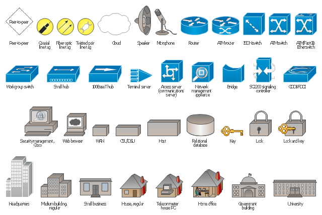
The vector stencils library "Logical symbols" contains 49 logical symbols for drawing logical network topology diagrams.
"Logical topology, or signal topology, is the arrangement of devices on a computer network and how they communicate with one another. How devices are connected to the network through the actual cables that transmit data, or the physical structure of the network, is called the physical topology. Physical topology defines how the systems are physically connected. It represents the physical layout of the devices on the network. The logical topology defines how the systems communicate across the physical topologies.
Logical topologies are bound to network protocols and describe how data is moved across the network. ... EXAMPLE : twisted pair Ethernet is a logical bus topology in a physical star topology layout. While IBM's token ring is a logical ring topology, it is physically set up in star topology." [Logical topology. Wikipedia]
The icons example "Logical symbols - Vector stencils library" was created using the ConceptDraw PRO diagramming and vector drawing software extended with the Computer and Networks solution from the Computer and Networks area of ConceptDraw Solution Park.
www.conceptdraw.com/ solution-park/ computer-and-networks
Coaxial Line Tag

Fiber Optic Line Tag

Twisted Pair Line Tag

SC2200 Signaling Controller

Bridge

Network Management Appliance

Access Server (Communications Server)
-logical-symbols---vector-stencils-library.png--diagram-flowchart-example.png)
Terminal Server

Web Browser

Security Management, Cisco

Lock and Key

Lock

Key

Relational Database

Host

CSU/DSU

WAN

University

Government building

Home Office

Telecommuter House PC

Medium Building, Regular

Headquarters, Subdued

House, Regular

Small Business

Network Connector

Dynamic Connector

Line Connector

Line-curve Connector

Bus

FDDI Ring

Peer-to-peer

Token-ring

Star

Comm-link

Curved Bus

Ethernet

Cloud

Speaker

Microphone

Router

ATM Router

ISDN Switch

ATM Switch

ATM/FastGB Etherswitch

Workgroup Switch

Small Hub

100BaseT Hub

CDDI-FDDI

The vector stencils library "Cable TV" contains 64 symbols of cable TV network equipment.
Use these shapes for drawing CATV system design floor plans, network topology diagrams, wiring diagrams and cabling layout schemes in the ConceptDraw PRO diagramming and vector drawing software.
The vector stencils library "Cable TV" is included in the Electric and Telecom Plans solution from the Building Plans area of ConceptDraw Solution Park.
Output Directional Tap 1

Output Directional Tap 2

Output Directional Tap 3

Output Directional Tap 4

Output Directional Tap 5

2-way Splitter

3-way Splitter

4-way Splitter

AC Power Block

Bond

Down Guy

Building Guy and Anchor

Rock Guy with Anchor

Down Guy with Anchor

Pole-to-Pole Guy

Sidewalk Down Guy with Anchor

Sidewalk Down Guy

Slack Span Messenger Wire

Tensioned Messenger Wire w/out cable

Tensioned Messenger Wire

Ground

Joint Usage (Power & Telephone Pole)
-cable-tv---vector-stencils-library.png--diagram-flowchart-example.png)
Joint Usgae Pole with Transformer

Strut

Tree Guy with Anchor

Push Brace (smaller pole in actual relative position)
-cable-tv---vector-stencils-library.png--diagram-flowchart-example.png)
Extension Arm

Built CATV Pole

Proposed CATV Pole

Directional Tap 1

Directional Tap 2

Manhole

Telephone Pole

Riser Pole

Vault Handheld

Fixed Equalizer

Fixed Flat Attenuators

Other Supporting Structures

Pedestal - Underground Routing

Power Pole

Direct Buried Underground Routing

Duct Line Underground Routing

Line Terminations

2-Way Optical Splice Location

3-Way Optical Splice Location

4-Way Optical Splice Location

> 4-Way Optical Splice Location

Optical Amplifier

Cable AC Power Combiner

Optical Fiber Cable

Optical Connector

Wavelength Demultiplexer

Wavelength Multiplexer

Optical Transmitter

Optical Transmitter

Optical Node

Optical Splitter

Headend (Signal Processing)
-cable-tv---vector-stencils-library.png--diagram-flowchart-example.png)
Node

Primary Hub

Secondary Hub

Coaxial Splice

Power Supply

Variable Equalizer

The design elements library "Cable TV" contains 64 symbols of CATV network equipment.
"Cable television is a system of distributing television programs to subscribers via radio frequency (RF) signals transmitted through coaxial cables or light pulses through fiber-optic cables. This contrasts with traditional broadcast television (terrestrial television) in which the television signal is transmitted over the air by radio waves and received by a television antenna attached to the television. FM radio programming, high-speed Internet, telephone service, and similar non-television services may also be provided through these cables.
The abbreviation CATV is often used for cable television." [Cable television. Wikipedia]
Use the shapes library "Cable TV" to draw CATV system design floor plans, network topology diagrams, wiring diagrams and cabling layout schemes using the ConceptDraw PRO diagramming and vector drawing software.
The vector stencils library "Cable TV" is included in the Electric and Telecom Plans solution from the Building Plans area of ConceptDraw Solution Park.
Cable TV symbols
.png--diagram-flowchart-example.png)
The vector stencils library "Logical symbols" contains 49 logical symbols for drawing logical network topology diagrams.
"Logical topology, or signal topology, is the arrangement of devices on a computer network and how they communicate with one another. How devices are connected to the network through the actual cables that transmit data, or the physical structure of the network, is called the physical topology. Physical topology defines how the systems are physically connected. It represents the physical layout of the devices on the network. The logical topology defines how the systems communicate across the physical topologies.
Logical topologies are bound to network protocols and describe how data is moved across the network. ... EXAMPLE : twisted pair Ethernet is a logical bus topology in a physical star topology layout. While IBM's token ring is a logical ring topology, it is physically set up in star topology." [Logical topology. Wikipedia]
The icons example "Logical symbols - Vector stencils library" was created using the ConceptDraw PRO diagramming and vector drawing software extended with the Computer and Networks solution from the Computer and Networks area of ConceptDraw Solution Park.
www.conceptdraw.com/ solution-park/ computer-and-networks
"Logical topology, or signal topology, is the arrangement of devices on a computer network and how they communicate with one another. How devices are connected to the network through the actual cables that transmit data, or the physical structure of the network, is called the physical topology. Physical topology defines how the systems are physically connected. It represents the physical layout of the devices on the network. The logical topology defines how the systems communicate across the physical topologies.
Logical topologies are bound to network protocols and describe how data is moved across the network. ... EXAMPLE : twisted pair Ethernet is a logical bus topology in a physical star topology layout. While IBM's token ring is a logical ring topology, it is physically set up in star topology." [Logical topology. Wikipedia]
The icons example "Logical symbols - Vector stencils library" was created using the ConceptDraw PRO diagramming and vector drawing software extended with the Computer and Networks solution from the Computer and Networks area of ConceptDraw Solution Park.
www.conceptdraw.com/ solution-park/ computer-and-networks
Coaxial Line Tag
Fiber Optic Line Tag
Twisted Pair Line Tag
SC2200 Signaling Controller
Bridge
Network Management Appliance
Access Server (Communications Server)
Terminal Server
Web Browser
Security Management, Cisco
Lock and Key
Lock
Key
Relational Database
Host
CSU/DSU
WAN
University
Government building
Home Office
Telecommuter House PC
Medium Building, Regular
Headquarters, Subdued
House, Regular
Small Business
Network Connector
Dynamic Connector
Line Connector
Line-curve Connector
Bus
FDDI Ring
Peer-to-peer
Token-ring
Star
Comm-link
Curved Bus
Ethernet
Cloud
Speaker
Microphone
Router
ATM Router
ISDN Switch
ATM Switch
ATM/FastGB Etherswitch
Workgroup Switch
Small Hub
100BaseT Hub
CDDI-FDDI
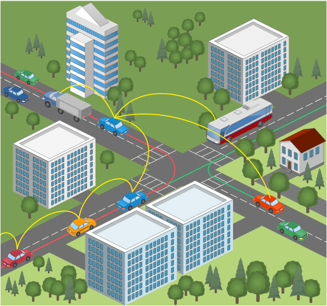
This vehicular network diagram sample was drawn on the base of picture illustrating the post "Intelligent transportation system" from the blog "Technology New Here".
"Intelligent transportation systems are projects that aim to integrate modern communication and information technology into existing transportation management systems in order to optimize vehicle life, fuel efficiency, safety, and traffic in urbanized cities.
The need for intelligent transportation systems stems from the fact that traffic congestion has been increasing all around the world because of increasing population, increasing amount of transportation vehicles and increasing urbanization."
[technologynewhere.wordpress.com/ 2010/ 05/ 12/ intelligent-transportation-system/ ]
The vehicular network diagram example "Intelligent transportation system" was created using the ConceptDraw PRO diagramming and vector drawing software extended with the Vehicular Networking solution from the Computer and Networks area of ConceptDraw Solution Park.
Vehicular network diagram
Used Solutions
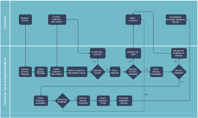
This swim lane diagram sample shows the telecom services process flow.
"Telecommunication is communication at a distance by technological means, particularly through electrical signals or electromagnetic waves. ...
Electrical and electromagnetic telecommunication technologies include telegraph, telephone, and teleprinter, networks, radio, microwave transmission, fiber optics, communications satellites and the Internet." [Telecommunication. Wikipedia]
"A telecommunications service provider or TSP is a type of communications service provider that has traditionally provided telephone and similar services. This category includes incumbent local exchange carriers, competitive local exchange carriers, and mobile wireless communication companies. ...
While some people use the terms "telecom service provider" and "communications service provider" interchangeably, the term TSP generally excludes Internet service providers (ISPs), cable companies, satellite TV, and managed service providers. ...
TSPs provide access to telephone and related communications services." [Telecommunications service provider. Wikipedia]
The cross-functional flowchart example "Providing telecom services" was created using the ConceptDraw PRO diagramming and vector drawing software extended with the Cross-Functional Flowcharts solution from the Business Processes area of ConceptDraw Solution Park.
Swin lane diagram
This vector stencils library contains 38 icons of logical symbols.
Use these shapes for drawing logical computer network topology diagrams using the ConceptDraw PRO diagramming and vector drawing software.
The clipart example "Design elements - Logical symbols" is included in the Computer and Networks solution from the Computer and Networks area of ConceptDraw Solution Park.
Logical network topology symbols
The vector stencils library "Rack diagrams" contains 55 hardware symbols for creating the server rack layout diagrams using the ConceptDraw PRO diagramming and vector drawing software.
"A 19-inch rack is a standardized frame or enclosure for mounting multiple equipment modules. Each module has a front panel that is 19 inches wide, including edges or ears that protrude on each side which allow the module to be fastened to the rack frame with screws. Equipment designed to be placed in a rack is typically described as rack-mount, rack-mount instrument, a rack mounted system, a rack mount chassis, subrack, rack mountable, or occasionally simply shelf. The industry standard rack cabinet is 42U tall." [19-inch rack. Wikipedia]
"A rack unit, U or RU is a unit of measure that describes the height of equipment designed to mount in a 19-inch rack or a 23-inch rack. The size of a piece of rack-mounted equipment is frequently described as a number in "U". For example, one rack unit is often referred to as "1U", 2 rack units as "2U" and so on.
A typical full size rack is 42U, which means it holds just over 6 feet of equipment, and a typical "half-height" rack would be 18-22U, or around 3 feet high." [Rack unit. Wikipedia]
The example "Design elements - Rack diagram" is included in the Rack Diagrams solution from the Computer and Networks area of ConceptDraw Solution Park.
Rack diagram elements
- Global vehicular network diagram template | UML Class Diagram ...
- Telecommunication Network Diagrams | Design elements ...
- Ethernet local area network layout floor plan | Network Layout Floor ...
- Fiber Optic Line Tag
- Draw Network Diagram based on Templates and Examples ...
- Global network diagram template | Computer and Networks Area ...
- Local network physical topology floor plan | ConceptDraw PRO ...
- Fiber Optic Cable Network Diagram Software
- Design Element: Network Layout for Network Diagrams | Basic ...
- Network Diagram Software Physical Network Diagram | Physical ...
- Wireless router network diagram | What Is a Wireless Network ...
- Cisco Optical . Cisco icons, shapes, stencils and symbols | Design ...
- Network Diagram Software LAN Network Diagrams & Diagrams for ...
- Network Diagramming Software for Design Cisco Network Diagrams ...
- Cisco Optical . Cisco icons, shapes, stencils and symbols | Cisco ...
- Wide area network (WAN) topology . Computer and Network Examples
- Independent regional networks diagram | Inter-vehicle ...
- Cable Network . Computer and Network Examples | Network ...
- Visible light communication | Vehicular ad-hoc network | Global ...
- Rack diagrams - Vector stencils library