How To use House Electrical Plan Software


The vector stenvils library "Outlets" contains 57 symbols of electrical outlets.
Use these shapes for drawing building interior design, electrical floor plans and layouts of AC power plugs and sockets in the ConceptDraw PRO diagramming and vector drawing software.
The vector stencils library "Outlets" is included in the Electric and Telecom Plans solution from the Building Plans area of ConceptDraw Solution Park.
Single Outlet

Single Outlet and Switch

Emergency Circuit Single Outlet

Duplex Convenience Outlet

Emergency Circuit Duplex Outlet

Weatherproof Convenience Outlet

Range Outlet

Switch and Convenience Outlet

Radio and Convenience Outlet

Radio Outlet

Dedicated Duplex Outlet

Duplex Ground Fault Interrupter

Split Wired Duplex Outlet

240v Outlet

Floor Mounted Outlet

Floor Special-purpose Outlet

Heavy Duty Outlet

Heavy Duty Outlet with Convenience Outlet

Triplex Outlet

Split Wired Triplex Outlet

Quadruplex Outlet

Emergency Circuit Quadruplex Outlet

Special-purpose Outlet

Duplex Special-purpose Outlet

Special-purpose connection or provision for connection

Multi-outlet Assembly

Data/voice, Power Floor Mounted Outlet

Clock Hanger Outlet, Mounted

Blanked Outlet

Drop Outlet

Electrical Outlet

Fan Outlet

Junction Box

Lamp Holder

Lamp holder with pull switch

Pull Switch

Vapor discharge lamp outlet

Exit Light Outlet

Floor Receptacle

Telephone outlet

Floor Phone Outlet

Wall Phone Outlet

Weatherproof Phone Outlet

Phone Feed

Computer Data Outlet

Television outlet

Floor TV Outlet

TV Feed

Weatherproof TV Outlet

TV and Phone Outlet

Door Phone Outlet

Fax Outlet

Fiber Outlet

Multi-Purpose Outlet

Local Area Network Outlet

Wall Mounted Data Outlet

Wall Mounted Data/Telephone Outlet

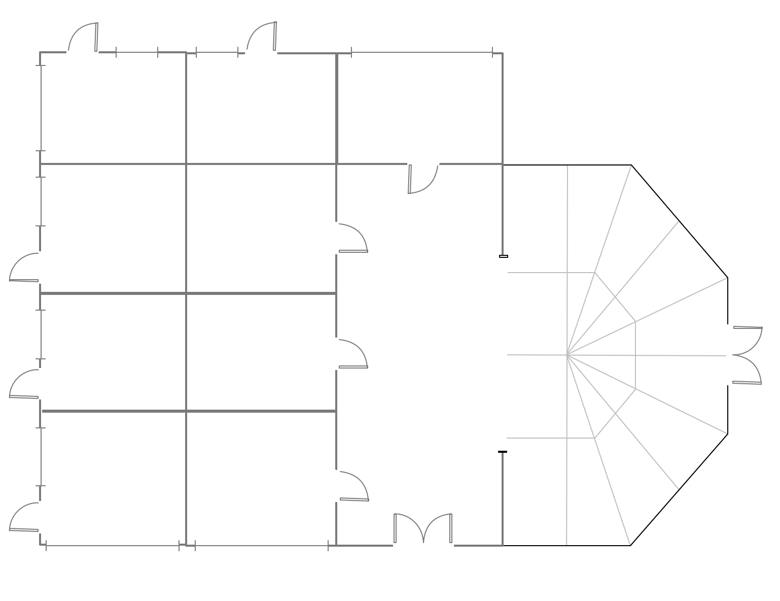
Mini Hotel Floor Plan. Floor Plan Examples
The vector stencil library "RCP-Electrical outlets" contains 43 socket symbols.
Use it to design your reflected ceiling plan with ConceptDraw DIAGRAM software.
"An electrical outlet or receptacle is a socket that connects an electrical device to an electricity supply. In buildings, electrical outlets are usually installed in the wall, although they can also be installed in the floor. Occasionally, they are found in the ceiling for powering devices such as garage door openers or neon signs in storefront windows. Different countries often have different outlet types and voltages. Adapters are available to convert between the different types." [Electrical outlet. Simple Wikipedia]
The receptacle symbols example "Design Elements - RCP-Electrical outlets" is included in Reflected Ceiling Plans solution from the Building Plans area of ConceptDraw Solution Park.
Vector stencils
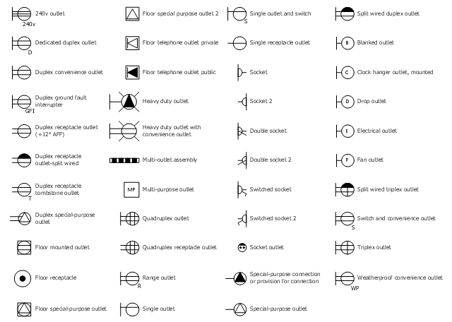
The vector stenvils library "Outlets" contains 57 symbols of electrical outlets for drawing building interior design, electrical floor plans and layouts of AC power plugs and sockets.
"AC power plugs and sockets are devices that allow electrically operated equipment to be connected to the primary alternating current (AC) power supply in a building. Electrical plugs and sockets differ in voltage and current rating, shape, size and type of connectors. The types used in each country are set by national standards, some of which are listed in the IEC technical report TR 60083, Plugs and socket-outlets for domestic and similar general use standardized in member countries of IEC.
Plugs and sockets for portable appliances started becoming available in the 1880s, to replace connections to light sockets with easier to use wall-mounted outlets. A proliferation of types developed to address the issues of convenience and protection from electric shock. Today there are approximately 20 types in common use around the world, and many obsolete socket types are still found in older buildings. Co-ordination of technical standards has allowed some types of plugs to be used over wide regions to facilitate trade in electrical appliances, and for the convenience of travellers and consumers of imported electrical goods. Some multi-standard sockets allow use of several different types of plugs; improvised or unapproved adapters between incompatible sockets and plugs may not provide the full safety and performance of an approved adapter." [AC power plugs and sockets. Wikipedia]
The example "Design elements - Outlets" was created using the ConceptDraw PRO diagramming and vector drawing software extended with the Electric and Telecom Plans solution from the Building plans area of ConceptDraw Solution Park.
Electrical outlet symbols

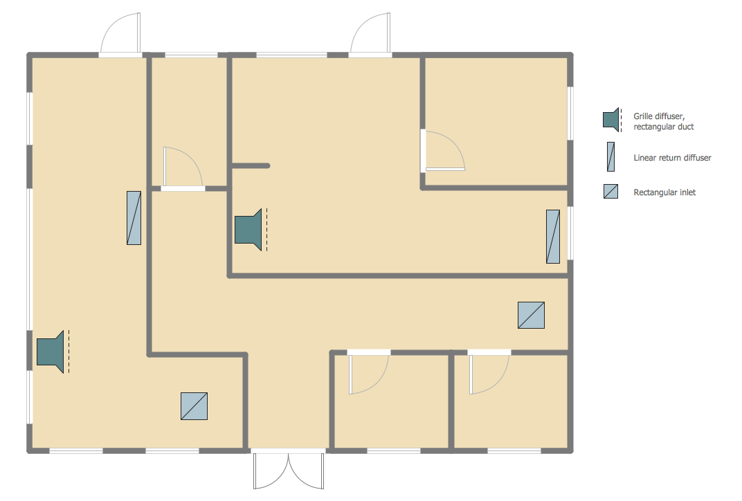
 Reflected Ceiling Plans
Reflected Ceiling Plans solution extends greatly the ConceptDraw DIAGRAM functionality with samples, templates and libraries of design elements for displaying the ceiling ideas for living room, bedroom, classroom, office, shop, restaurant, and many other premises. It is an effective tool for architects, designers, builders, electricians, and other building-related people to represent their ceiling design ideas and create Reflected Ceiling plan or Reflective Ceiling plan, showing the location of light fixtures, lighting panels, drywall or t-bar ceiling patterns, HVAC grilles or diffusers that may be suspended from the ceiling. Being professional-looking and vivid, these plans perfectly reflect your ceiling ideas and can be presented to the client, in reports, in presentations, on discussions with colleagues, or successfully published in modern print or web editions.
Reflective Ceiling Plan
 Electric and Telecom Plans
The Electric and Telecom Plans solution providing the electric and telecom-related stencils, floor plan electrical symbols and pre-made examples is useful for electricians, interior designers, telecommunications managers, builders and other technicians when creating the electric visual plans and telecom drawings, home electrical plan, residential electric plan, telecom wireless plan, electrical floor plans whether as a part of the building plans or the independent ones.
The vector stencils library "Transmission paths" contains 43 symbols of power transmission paths, electronic circuits, bus connectors and elbows, terminals, junctions, and concentrators.
Use it to annotate electrical diagrams, electronic schematics and circuit diagrams.
"A physical medium in data communications is the transmission path over which a signal propagates.
Many transmission media are used as communications channel.
For telecommunications purposes in the United States, Federal Standard 1037C, transmission media are classified as one of the following:
(1) Guided (or bounded) - waves are guided along a solid medium such as a transmission line.
(2) Wireless (or unguided) - transmission and reception are achieved by means of an antenna.
One of the most common physical medias used in networking is copper wire. Copper wire to carry signals to long distances using relatively low amounts of power. The unshielded twisted pair (UTP) is eight strands of copper wire, organized into four pairs.
Another example of a physical medium is optical fiber, which has emerged as the most commonly used transmission medium for long-distance communications. Optical fiber is a thin strand of glass that guides light along its length.
Multimode and single mode are two types of commonly used optical fiber. Multimode fiber uses LEDs as the light source and can carry signals over shorter distances, about 2 kilometers. Single mode can carry signals over distances of tens of miles.
Wireless media may carry surface waves or skywaves, either longitudinally or transversely, and are so classified.
In both communications, communication is in the form of electromagnetic waves. With guided transmission media, the waves are guided along a physical path; examples of guided media include phone lines, twisted pair cables, coaxial cables, and optical fibers. Unguided transmission media are methods that allow the transmission of data without the use of physical means to define the path it takes. Examples of this include microwave, radio or infrared. Unguided media provide a means for transmitting electromagnetic waves but do not guide them; examples are propagation through air, vacuum and seawater.
The term direct link is used to refer to the transmission path between two devices in which signals propagate directly from transmitters to receivers with no intermediate devices, other than amplifiers or repeaters used to increase signal strength. This term can apply to both guided and unguided media.
A transmission may be simplex, half-duplex, or full-duplex.
In simplex transmission, signals are transmitted in only one direction; one station is a transmitter and the other is the receiver. In the half-duplex operation, both stations may transmit, but only one at a time. In full duplex operation, both stations may transmit simultaneously. In the latter case, the medium is carrying signals in both directions at same time." [Transmission medium. Wikipedia]
The shapes example "Design elements - Transmission paths" was drawn using the ConceptDraw PRO diagramming and vector drawing software extended with the Electrical Engineering solution from the Engineering area of ConceptDraw Solution Park.
Transmission path symbols

Electrical Symbols — Stations

- Electrical Drawing Of Duplex Sample
- Duplex Electrical Plan
- Duplex Convenience Outlet Electrical Symbol
- Complete Duplex Plan With Mechanical And Electrical Drawings
- Electrical Drawings For Duplex
- Show A Duplex Ground Floor Plan With Electrical Installation Symbols
- Duplex Electrical Drawing Plan
- Design elements - Outlets | Duplex Receptacle Symbol Iec
- How To use House Electrical Plan Software | Network Diagramming ...
- Electrical Engineering Plan Duplex