The vector stencils library "UML use case diagrams" contains 25 symbols for the ConceptDraw PRO diagramming and vector drawing software.
"Use case diagrams are usually referred to as behavior diagrams used to describe a set of actions (use cases) that some system or systems (subject) should or can perform in collaboration with one or more external users of the system (actors). Each use case should provide some observable and valuable result to the actors or other stakeholders of the system. ...
Use case diagrams are in fact twofold - they are both behavior diagrams, because they describe behavior of the system, and they are also structure diagrams - as a special case of class diagrams where classifiers are restricted to be either actors or use cases related to each other with associations. ...
Use case is usually shown as an ellipse containing the name of the use case. ...
Name of the use case could also be placed below the ellipse. ...
If a subject (or system boundary) is displayed, the use case ellipse is visually located inside the system boundary rectangle. Note, that this does not necessarily mean that the subject classifier owns the contained use cases, but merely that the use case applies to that classifier. ...
A list of use case properties - operations and attributes - could be shown in a compartment within the use case oval below the use case name. ...
Use case with extension points may be listed in a compartment of the use case with the heading extension points. ...
A use case can also be shown using the standard rectangle notation for classifiers with an ellipse icon in the upper right-hand corner of the rectangle and with optional separate list compartments for its features. ...
Subject (sometimes called a system boundary) is presented by a rectangle with subject's name, associated keywords and stereotypes in the upper left corner. Use cases applicable to the subject are located inside the rectangle and actors - outside of the system boundary. ...
Standard UML notation for actor is "stick man" icon with the name of the actor above or below of the icon. Actor names should follow the capitalization and punctuation guidelines for classes. The names of abstract actors should be shown in italics. ...
Custom icons that convey the kind of actor may also be used to denote an actor, such as using a separate icon(s) for non-human actors. ...
An actor may also be shown as a class rectangle with the standard keyword «actor», having usual notation for class compartments ...
An actor can only have binary associations to use cases, components, and classes. ...
An association between an actor and a use case indicates that the actor and the use case somehow interact or communicate with each other.
Only binary associations are allowed between actors and use cases.
An actor could be associated to one or several use cases. ...
A use case may have one or several associated actors." [uml-diagrams.org/ use-case-diagrams.html]
The example "Design elements - UML use case diagrams" is included in the Rapid UML solution from the Software Development area of ConceptDraw Solution Park.
UML use case diagram symbols

The vector stencils library "UML composite structure diagrams" contains 36 symbols for the ConceptDraw PRO diagramming and vector drawing software.
"The key composite structure entities identified in the UML 2.0 specification are structured classifiers, parts, ports, connectors, and collaborations.
(1) Part : A part represents a role played at runtime by one instance of a classifier or by a collection of instances. The part may only name the role, it may name an abstract superclass, or it may name a specific concrete class. The part can include a multiplicity factor, such as the [0..*] shown for Viewer in the diagram.
(2) Port : A port is an interaction point that can be used to connect structured classifiers with their parts and with the environment. Ports can optionally specify the services they provide and the services they require from other parts of the system. In the diagram, each of the small squares is a port. Each port has a type and is labelled with a name, such as "var", "indVar1", or "view" in the diagram. Ports may contain a multiplicity factor, for example.
Ports can either delegate received requests to internal parts, or they can deliver these directly to the behavior of the structured classifier that the port is contained within. Public ports that are visible in the environment are shown straddling the boundary, while protected ports that are not visible in the environment are shown inside the boundary. All the ports in the diagram are public, except for the view port along the right boundary of FibonacciSystem.
(3) Connector : A connector binds two or more entities together, allowing them to interact at runtime. The connector is shown as a line between some combination of parts, ports and structured classifiers. The diagram shows three connectors between ports, and one connector between a structured classifier and a part.
(4) Collaboration : A collaboration is generally more abstract than a structured classifier. It is shown as a dotted oval containing roles that instances can play in the collaboration.
(5) Structured classifier : A StructuredClassifier represents a class, often an abstract class, whose behavior can be completely or partially described through interactions between parts." [Composite structure diagram. Wikipedia]
The example "Design elements - UML composite structure diagrams" is included in the Rapid UML solution from the Software Development area of ConceptDraw Solution Park.
UML composite structure diagram symbols

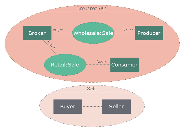
"A broker is an individual or party (brokerage firm) that arranges transactions between a buyer and a seller for a commission when the deal is executed. A broker who also acts as a seller or as a buyer becomes a principal party to the deal. Distinguish agent - one who acts on behalf of a principal. ...
In general a broker is an independent agent used extensively in some industries. A broker's prime responsibility is to bring sellers and buyers together and thus a broker is the third-person facilitator between a buyer and a seller. An example would be a real estate broker who facilitates the sale of a property.
Brokers also can furnish market information regarding prices, products, and market conditions. Brokers may represent either the seller (90% of the time) or the buyer (10%) but not both at the same time. An example would be a stockbroker, who makes the sale or purchase of securities on behalf of his client. Brokers play a huge role in the sale of stocks, bonds, and other financial services." [Broker. Wikipedia]
The UML composite structure diagram example "Sale process" was created using the ConceptDraw PRO diagramming and vector drawing software extended with the Rapid UML solution from the Software Development area of ConceptDraw Solution Park.
UML composite structure diagram
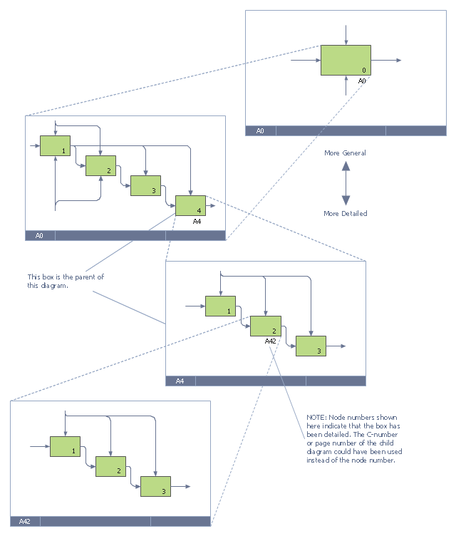
This IDEF0 diagram example was redesigned from the Wikimedia Commons file: 6 Decomposition Structure.svg.
[commons.wikimedia.org/ wiki/ File:6_ Decomposition_ Structure.svg]
"Functional decomposition refers broadly to the process of resolving a functional relationship into its constituent parts in such a way that the original function can be reconstructed (i.e., recomposed) from those parts by function composition. In general, this process of decomposition is undertaken either for the purpose of gaining insight into the identity of the constituent components (which may reflect individual physical processes of interest, for example), or for the purpose of obtaining a compressed representation of the global function, a task which is feasible only when the constituent processes possess a certain level of modularity (i.e., independence or non-interaction). Interactions between the components are critical to the function of the collection. All interactions may not be observable, but possibly deduced through repetitive perception, synthesis, validation and verification of composite behavior." [Functional decomposition. Wikipedia]
The example "IDEF0 diagram - Decomposition structure" was created using the ConceptDraw PRO diagramming and vector drawing software extended with the solution "IDEF Business Process Diagrams" from the area "Business Processes" of ConceptDraw Solution Park.
IDEF0 business process diagram
The vector stencils library "Bushes and trees" contains 57 clipart images of bushes and trees. Use it to create your landscape design and garden plan.
"A shrub is a small to medium sized woody plant. It is distinguished from a tree by its multiple stems and shorter height, usually under 6 m (20 ft) tall. Plants of many species may grow either into shrubs or trees, depending on their growing conditions. Small, low shrubs, generally less than 2 m (6.6 ft) tall, such as lavender, periwinkle and most small garden varieties of roses, are often termed subshrubs or bushes.
An area of cultivated shrubs in a park or a garden is known as a shrubbery. When clipped as topiary, suitable species or varieties of shrubs develop dense foliage and many small leafy branches growing close together. Many shrubs respond well to renewal pruning, in which hard cutting back to a 'stool' results in long new stems known as "canes". Other shrubs respond better to selective pruning to reveal their structure and character.
Shrubs in common garden practice are generally considered broad-leaved plants, though some smaller conifers such as Mountain Pine and Common Juniper are also shrubby in structure. Species that grow into a shrubby habit may be either deciduous or evergreen." [Shrub. Wikipedia]
The bushes clipart example "Design elements - Bushes and trees (bushes)" was created using the ConceptDraw PRO diagramming and vector drawing software extended with the Landscape & Garden solution from the Building Plans area of ConceptDraw Solution Park.
Bushes clipart
.png--diagram-flowchart-example.png)
IDEF1 standard

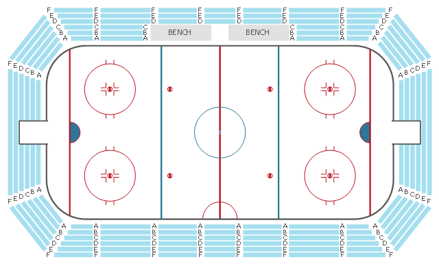
This seating plan sample shows the stadium seat layout.
"A modern stadium (plural stadiums/ stadia) is a place or venue for (mostly) outdoor sports, concerts, or other events and consists of a field or stage either partly or completely surrounded by a structure designed to allow spectators to stand or sit and view the event. ...
Spectator areas and seating.
An "all-seater" stadium has seats for all spectators. Other stadiums are designed so that all or some spectators stand to view the event. The term "all-seater" is not common in the U.S., perhaps because very few American stadiums have sizeable standing-only sections. ...
The spectator areas of a stadium may be referred to as bleachers, especially in the U.S., or as terraces, especially in the United Kingdom, but also in some American baseball parks, as an alternative to the term tier. Originally set out for standing room only, they are now usually equipped with seating. Either way, the term originates from the step-like rows which resemble agricultural terraces. Related, but not precisely the same, is the use of the word terrace to describe a sloping portion of the outfield in a baseball park, possibly, but not necessarily for seating, but for practical or decorative purposes. ... Many stadiums make luxury suites or boxes available to patrons at high prices. These suites can accommodate fewer than 10 spectators or upwards of 30 depending on the venue. Luxury suites at events such as the Super Bowl can cost hundreds of thousands of dollars." [Stadium. Wikipedia]
The seat layout example "Stadium seating plan" was created using the ConceptDraw PRO diagramming and vector drawing software extended with the Seating Plans solution from the Building Plans area of ConceptDraw Solution Park.
Seat layout
 Active Directory Diagrams
Active Directory Diagrams solution extends ConceptDraw PRO software with samples, templates and libraries of vector stencils for drawing the AD diagrams to visualize the detail structures of the Microsoft Windows networks.
- Flowchart Maker | Design elements - UML composite structure ...
- UML composite structure diagram - Sale process | Use Case ...
- Use Case Diagram Notations
- Design elements - UML use case diagrams | UML component ...
- Use Case Diagram Symbols
- UML Diagram Types List | UML Diagrams with ConceptDraw PRO ...
- UML Flowchart Symbols | Design elements - UML use case ...
- How To Use Case Diagram
- UML Use Case Diagram Example. Services UML Diagram. ATM ...
- Diagramming Software for UML Composite Structure Diagrams ...
- Design elements - UML use case diagrams | UML Sequence ...
- Diagramming Software for Design UML Use Case Diagrams | UML ...
- Data structure diagram with ConceptDraw PRO | Presenting ...
- UML class diagram - Template | Design elements - UML class ...
- UML Diagram | Unified Modeling Language Diagram | Design ...
- Design elements - UML use case diagrams
- UML Notation | Entity-Relationship Diagram (ERD) | UML Diagram ...
- Diagramming Software for UML Composite Structure Diagrams ...
- Design elements - UML composite structure diagrams | Design ...
- Process Flowchart | Data structure diagram with ConceptDraw PRO ...