Interior Design. Registers, Drills and Diffusers — Design Elements

Mechanical Drawing Symbols

The vector stencil library "HVAC ductwork" contains 63 duct and vent symbols.
Use it for drawing HVAC system diagrams, heating, ventilation, air conditioning, refrigeration, automated building control, and environmental control design floor
plans and equipment layouts.
"Ducts are used in heating, ventilation, and air conditioning (HVAC) to deliver and remove air. These needed airflows include, for example, supply air, return air, and exhaust air. Ducts also deliver, most commonly as part of the supply air, ventilation air. As such, air ducts are one method of ensuring acceptable indoor air quality as well as thermal comfort.
A duct system is often called ductwork. Planning ('laying out'), sizing, optimizing, detailing, and finding the pressure losses through a duct system is called duct design." [Duct (HVAC). Wikipedia]
The vector stencils example "Design elements - HVAC ductwork" is included in HVAC Plans solution from the Building Plans area of ConceptDraw Solution Park.
HVAC ductwork symbols

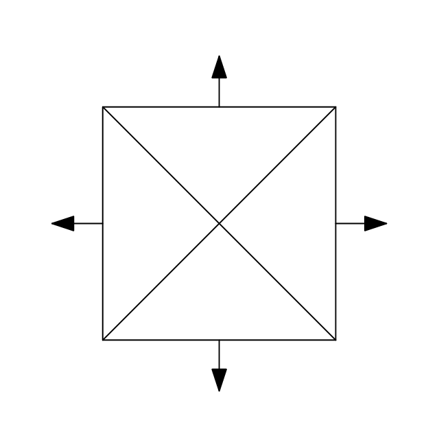
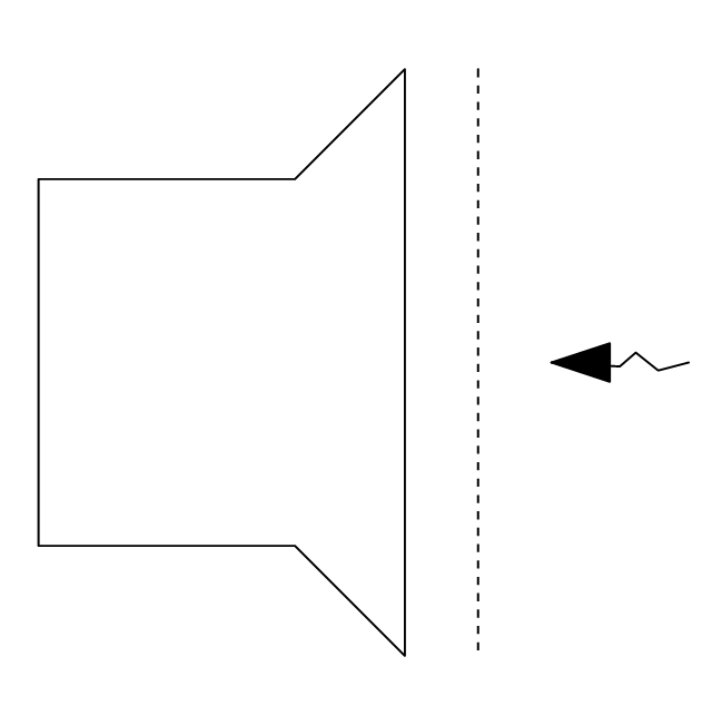
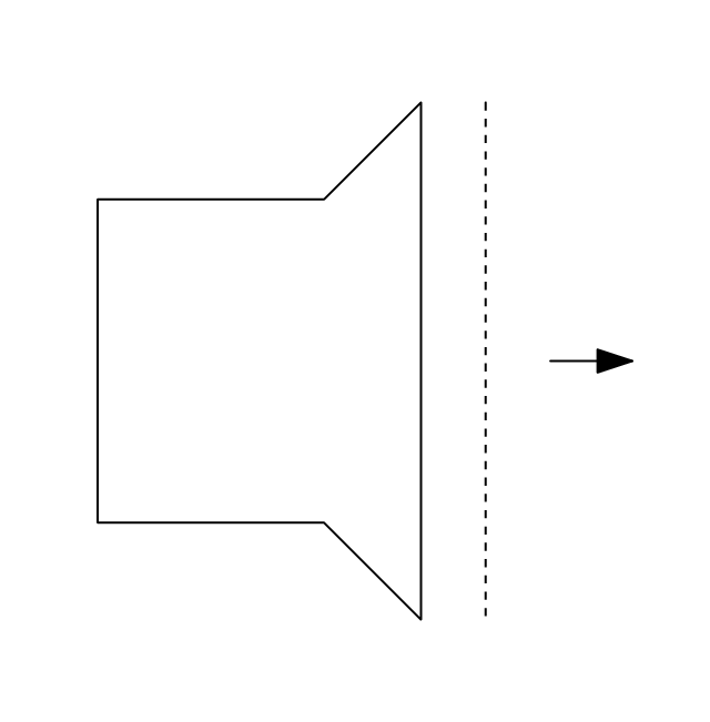
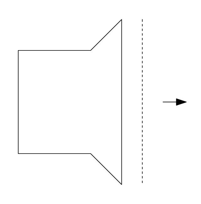
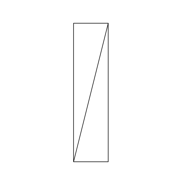
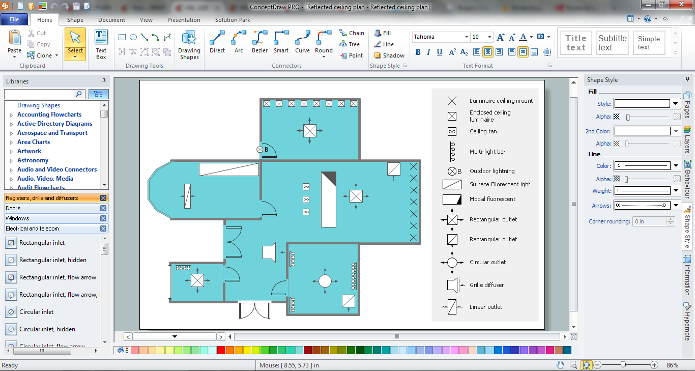
The vector stencils library "Registers, drills and diffusers" contains 47 shapes of rectangular, circular, linear and troffer air handling inlet/ outlet components, registers, drills and diffusers. Use it for drawing reflected ceiling plans and HVAC plans in the ConceptDraw PRO diagramming and vector drawing software extended with the Reflected Ceiling Plans solution from the Building Plans area of ConceptDraw Solution Park.
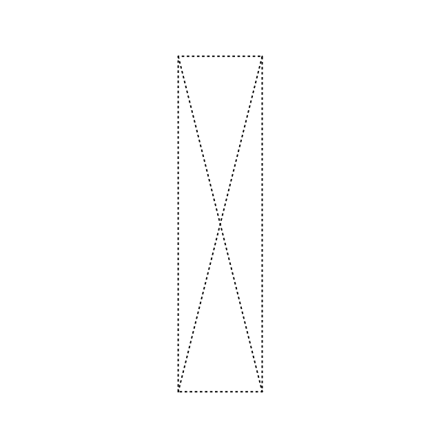
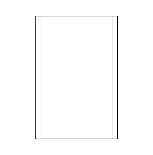
Rectangular inlet
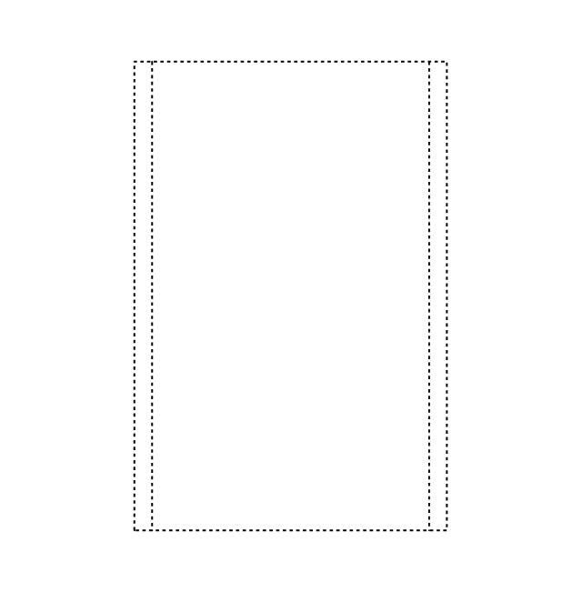
Rectangular inlet, hidden
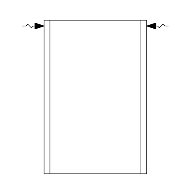
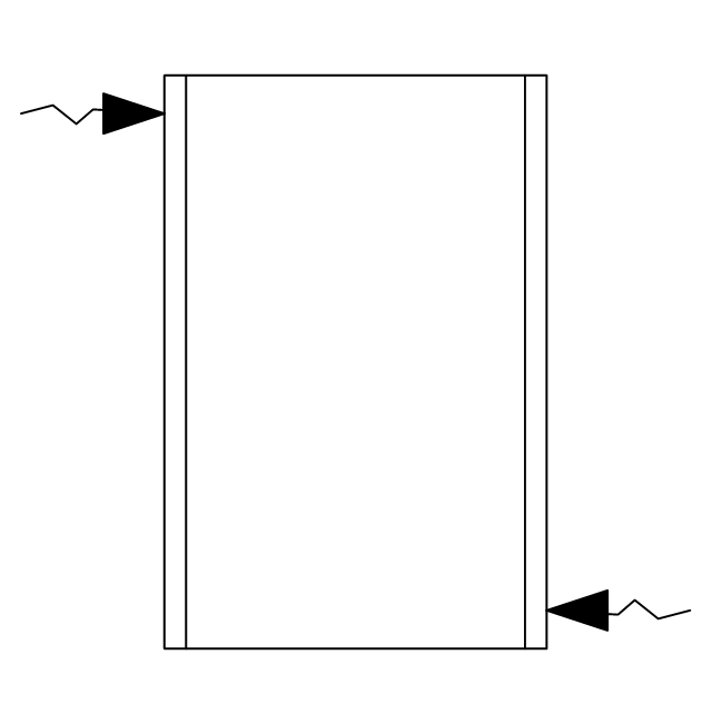
Rectangular inlet, flow arrow
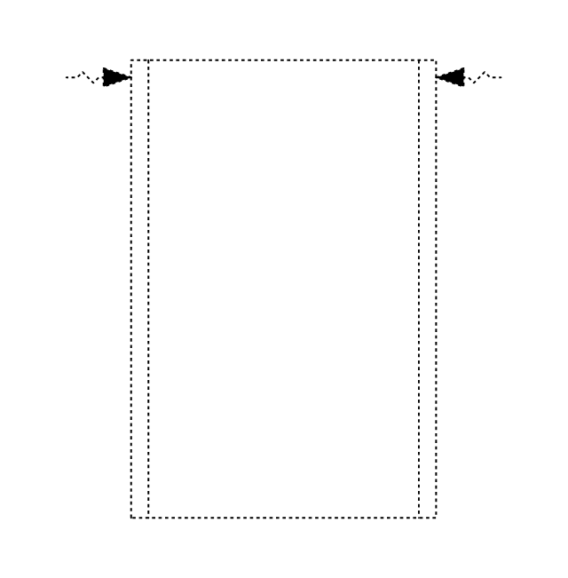
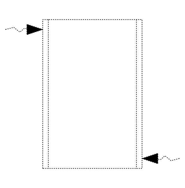
Rectangular inlet, flow arrow, hidden
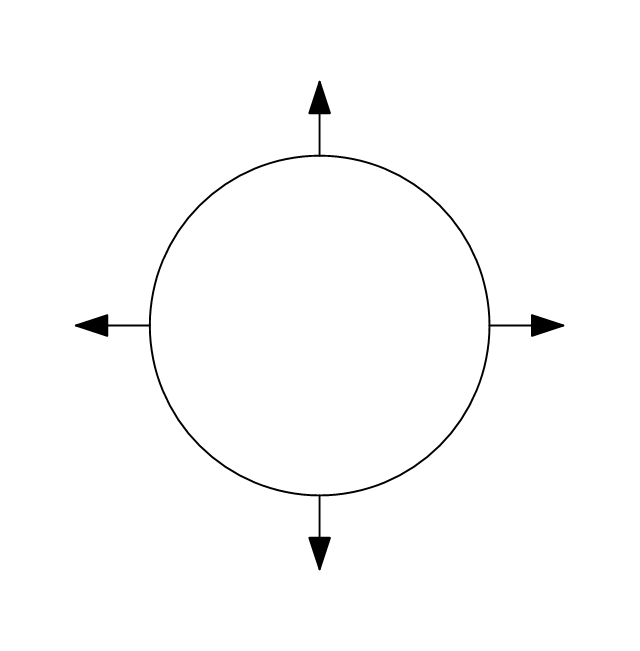
Circular inlet
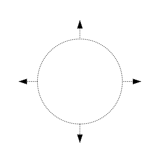
Circular inlet, hidden
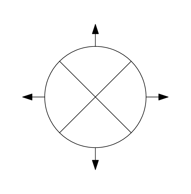
Circular inlet, flow arrow
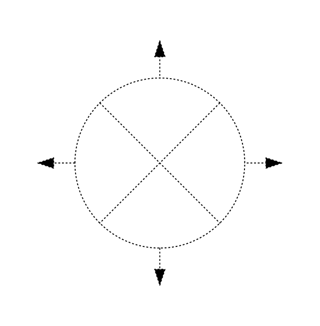
Circular inlet, flow arrow, hidden
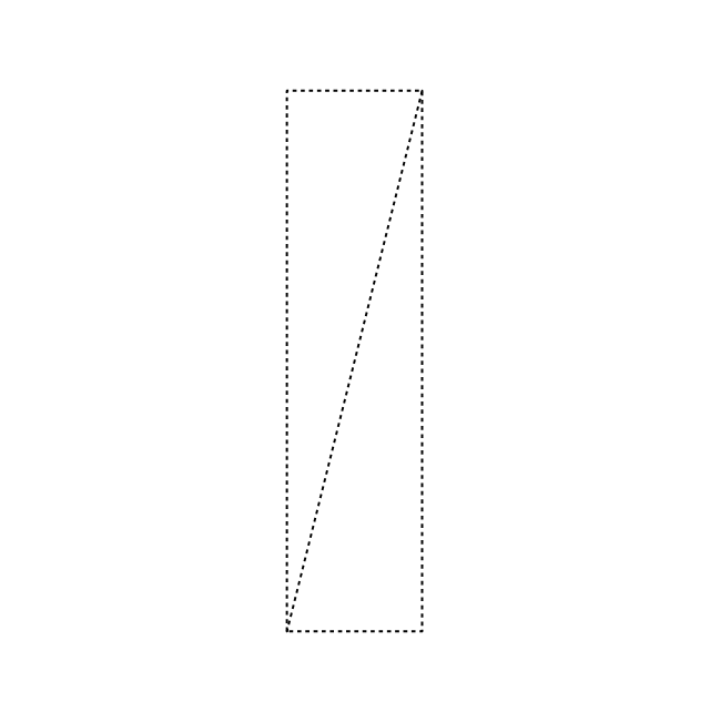
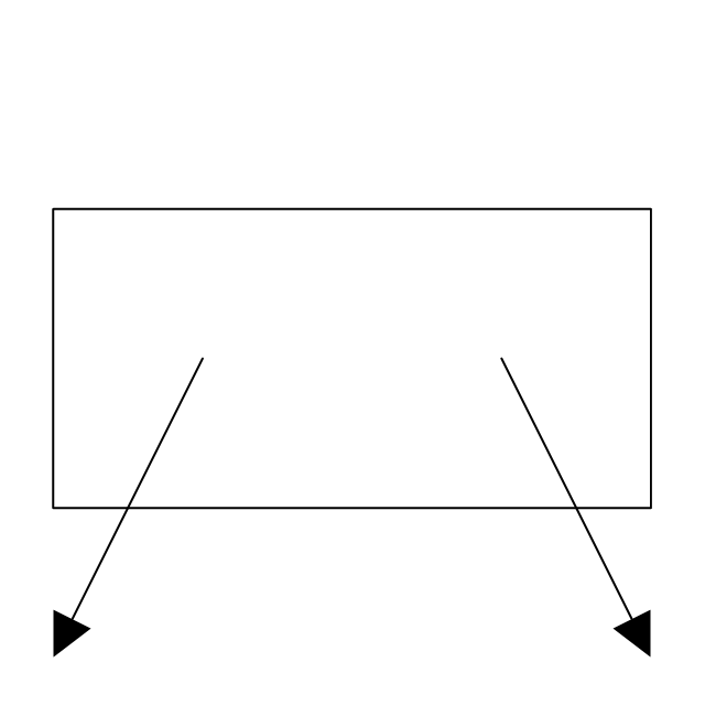
Rectangular outlet
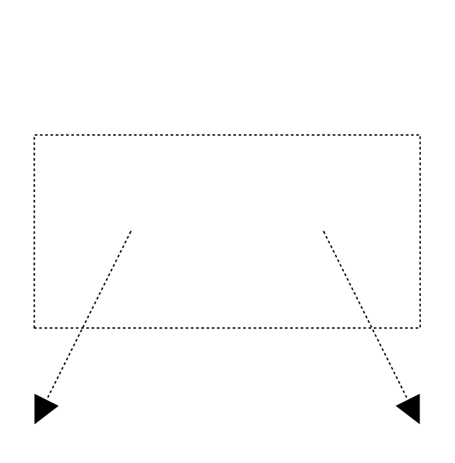
Rectangular outlet, hidden
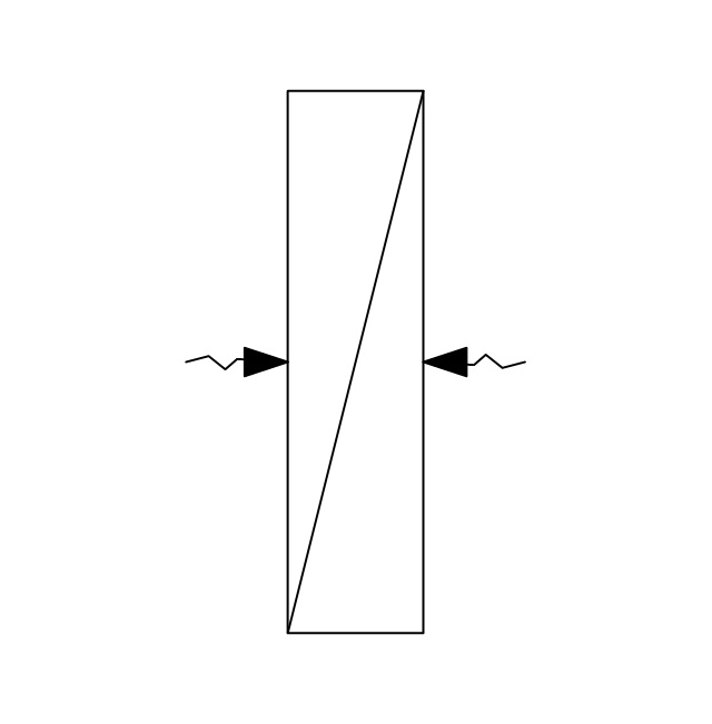
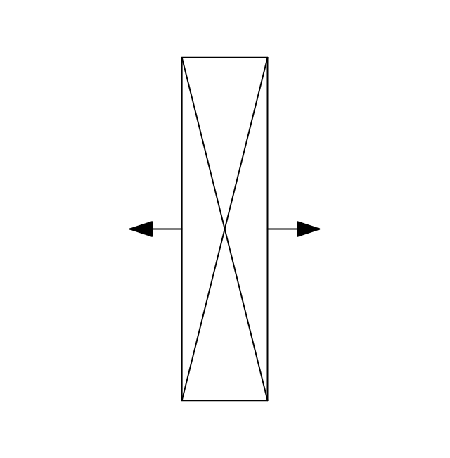
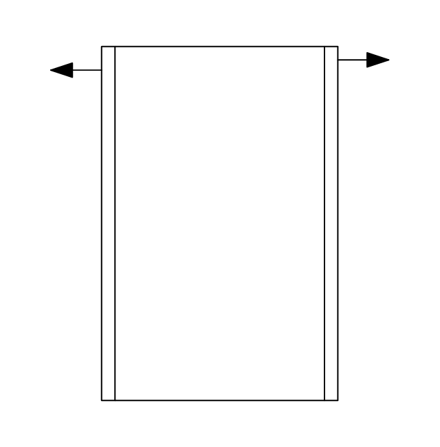
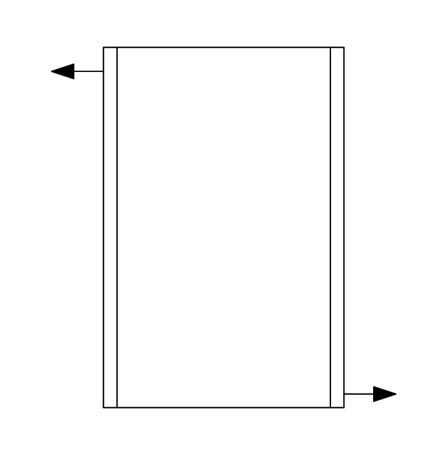
Rectangular outlet, flow arrows
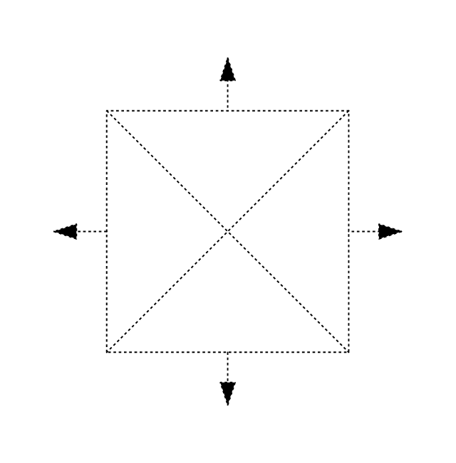
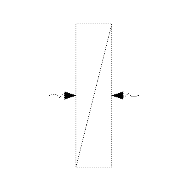
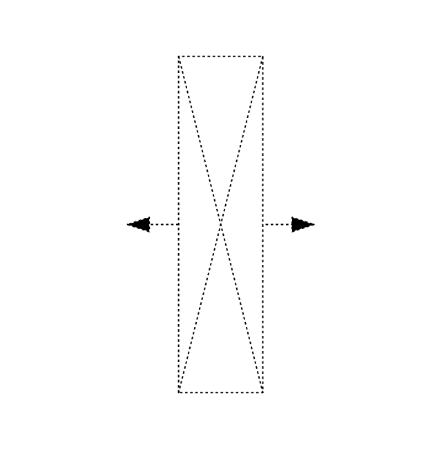
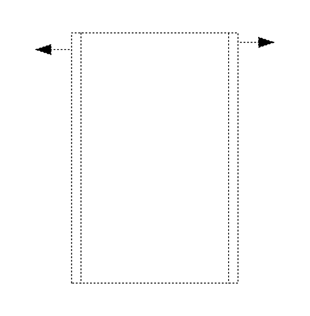
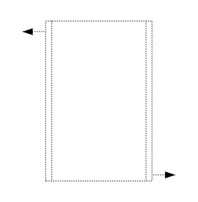
Rectangular outlet, flow arrows, hidden
Circular outlet
Circular outlet, hidden
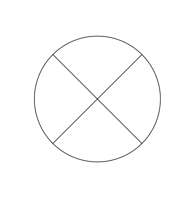
Circular outlet, flow arrows
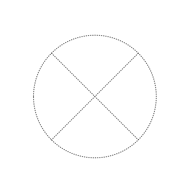
Circular outlet, flow arrows, hidden
Grille diffuser, rectangular duct
Grille diffuser, circular duct

Return grille diffuser, rectangular duct
Return grille diffuser, circular duct
Supply grille diffuser, rectangular duct
Supply grille diffuser, circular duct
Linear return diffuser
Linear return diffuser, hidden
Linear supply diffuser

Linear supply diffuser, hidden
Linear return diffuser, flow arrows
Linear return diffuser, flow arrows, hidden
Linear supply diffuser, flow arrows
Linear supply diffuser, flow arrows, hidden
Troffer inlet / outlet
Troffer inlet / outlet, hidden
Troffer inlet, return diffuser
Troffer inlet, return diffuser, hidden
Troffer inlet, supply diffuser
Troffer inlet, supply diffuser, hidden
Troffer outlet, return diffuser
Troffer outlet, return diffuser, hidden
Troffer outlet, supply diffuser
Troffer outlet, supply diffuser, hidden
Circular outlet
Circular outlet, hidden
Grille
Grille, hidden
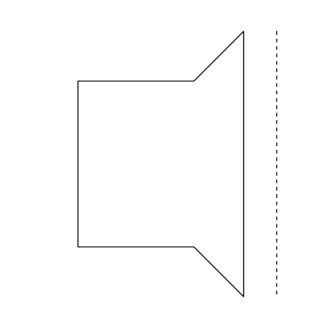
Grille (side)
-registers,-drills-and-diffusers---vector-stencils-library.png--diagram-flowchart-example.png)
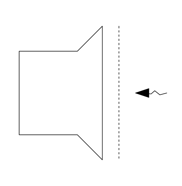
Grille (side), return diffuser
,-return-diffuser-registers,-drills-and-diffusers---vector-stencils-library.png--diagram-flowchart-example.png)
Grille (side), supply diffuser
,-supply-diffuser-registers,-drills-and-diffusers---vector-stencils-library.png--diagram-flowchart-example.png)
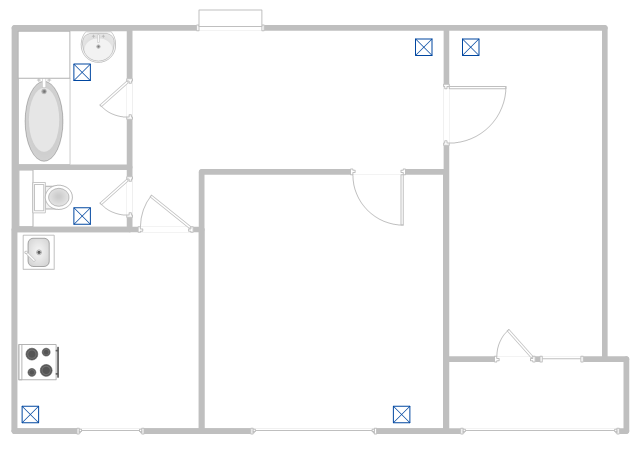
This apartment HVAC (Heating, Ventilating and Air Conditioning) plan shows the layout of exhaust ventilation duct outlet diffusers.
"Ventilation is the intentional introduction of outside air into a space. Ventilation is mainly used to control indoor air quality by diluting and displacing indoor pollutants; it can also be used for purposes of thermal comfort or dehumidification when the introduction of outside air will help to achieve desired indoor psychrometric conditions.
The intentional introduction of outside air can be categorized as either mechanical ventilation, or natural ventilation. Mechanical ventilation uses fans to drive the flow of outside air into a building. This may be accomplished by pressurization (in the case of positively pressurized buildings), or by depressurization (in the case of exhaust ventilation systems). Many mechanically ventilated buildings use a combination of both, with the ventilation being integrated into the HVAC system." [Ventilation (architecture). Wikipedia]
The floor plan example "Apartment HVAC plan" was created using the ConceptDraw DIAGRAM diagramming and vector drawing software extended with the HVAC Plans solution from the Building Plans area of ConceptDraw Solution Park.
Floor plan
Building Drawing. Design Element — Plumbing

Ceiling Ideas For Living Room
This mechanical room HVAC plan sample shows the layout of air handler (air handling unit, AHU) equipment: mixing chamber, air filter, fan (blower), heat exchanger coil, diffusers.
"Ventilating (the V in HVAC) is the process of "changing" or replacing air in any space to provide high indoor air quality (i.e. to control temperature, replenish oxygen, or remove moisture, odors, smoke, heat, dust, airborne bacteria, and carbon dioxide). Ventilation is used to remove unpleasant smells and excessive moisture, introduce outside air, to keep interior building air circulating, and to prevent stagnation of the interior air.
Ventilation includes both the exchange of air to the outside as well as circulation of air within the building. It is one of the most important factors for maintaining acceptable indoor air quality in buildings. Methods for ventilating a building may be divided into mechanical/ forced and natural types.
"Mechanical" or "forced" ventilation is used to control indoor air quality. Excess humidity, odors, and contaminants can often be controlled via dilution or replacement with outside air. However, in humid climates much energy is required to remove excess moisture from ventilation air.
Ventilation increases the energy needed for heating or cooling, however heat recovery ventilation can be used to mitigate the energy consumption. This involves heat exchange between incoming and outgoing air. Energy recovery ventilation additionally includes exchange of humidity." [Ventilation (architecture). Wikipedia]
The HVAC floor plan example "Ventilation system layout" was created using the ConceptDraw DIAGRAM diagramming and vector drawing software extended with the HVAC Plans solution from the Building Plans area of ConceptDraw Solution Park.
HVAC floor plan

This reflected ceiling plan sample was created on the base of the article "How to Read a Reflected Ceiling Plan" from wikiHow.com.
"A reflected ceiling plan (RCP) is a drawing, which shows the items that are located on the ceiling of a room or space. It is referred to as a reflected ceiling plan since it is drawn to display a view of the ceiling as if it was reflected onto a mirror on the floor. This way the reflected ceiling plan has the same orientation as the floor plan associated with it. It is as if the ceiling was see-through and you could see right through it to the floor below. Architects and interior designers draw reflected ceiling plans when designing spaces." [wikihow.com/ Read-a-Reflected-Ceiling-Plan]
The HVAC layout example "RCP- HVAC layout" was created using the ConceptDraw DIAGRAM diagramming and vector drawing software extended with the Reflected Ceiling Plans solution from the Building Plans area of ConceptDraw Solution Park.
Reflected ceiling plan

Living Room. Piano in plan

- Design elements - HVAC ductwork | Building Drawing Software for ...
- Airconditioning Plannimg Diagram
- HVAC Plans | How to Create a HVAC Plan | Air handler- HVAC plan ...
- Building Drawing Software for Design Registers, Drills and Diffusers ...
- Hvac Equipment Layout
- Design elements - HVAC ductwork | Ductwork layout | Building ...
- Design elements - HVAC ductwork | Air handler- HVAC plan ...
- Building Drawing Software for Design Registers, Drills and Diffusers ...
- Simple Diagram For Grills And Diffuser
- Design elements - HVAC ductwork | Interior Design Registers, Drills ...