This engineering drawing present weld type symbols and fillet weld symbols.
The weld type symbol is typically placed above or below the center of the reference line, depending on which side of the joint it's on. The symbol is interpreted as a simplified cross-section of the weld.
"Fillet welding refers to the process of joining two pieces of metal together whether they be perpendicular or at an angle. These welds are commonly referred to as Tee joints which are two pieces of metal perpendicular to each other or Lap joints which are two pieces of metal that overlap and are welded at the edges. The weld is aesthetically triangular in shape and may have a concave, flat or convex surface depending on the welder’s technique. Welders use fillet welds when connecting flanges to pipes, welding cross sections of infrastructure, and when fastening metal by bolts isn't strong enough." [Fillet weld. Wikipedia]
The engineering drawing example Welding symbols is included in the Mechanical Engineering solution from Engineering area of ConceptDraw Solution Park.
Welding joint symbols

"A welding joint is a point or edge where two or more pieces of metal or plastic are joined together. They are formed by welding two or more workpieces (metal or plastic) according to a particular geometry. Five types of joints referred to by the American Welding Society: butt, corner, edge, lap, and tee. These configurations may have various configurations at the joint where actual welding can occur." [Welding joint. Wikipedia]
The engineering drawing example "Welded joints types" was created using the ConceptDraw PRO diagramming and vector drawing software extended with the Mechanical Engineering solution from the Engineering area of ConceptDraw Solution Park.
The engineering drawing example "Welded joints types" was created using the ConceptDraw PRO diagramming and vector drawing software extended with the Mechanical Engineering solution from the Engineering area of ConceptDraw Solution Park.
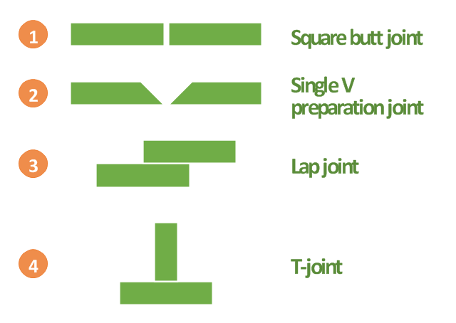
Welding joints
"A welding joint is a point or edge where two or more pieces of metal or plastic are joined together. They are formed by welding two or more workpieces (metal or plastic) according to a particular geometry. Five types of joints referred to by the American Welding Society: butt, corner, edge, lap, and tee. These configurations may have various configurations at the joint where actual welding can occur." [Welding joint. Wikipedia]
This engineering drawing example was redesigned using the ConceptDraw PRO diagramming and vector drawing software from the Wikimedia Commons file: Common joint types.png.
[commons.wikimedia.org/ wiki/ File:Common_ joint_ types.png]
This file is licensed under the Creative Commons Attribution-Share Alike 3.0 Unported license.
[creativecommons.org/ licenses/ by-sa/ 3.0/ deed.en]
The engineering drawing example "Common joint types" is included in the Mechanical Engineering solution from the Engineering area of ConceptDraw Solution Park.
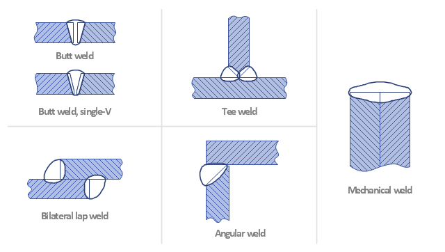
Welding joint types
The vector stencils library "Welding" contains 38 welding joint symbols to identify fillets, contours, resistance seams, grooves, surfacing, and backing.
Use it to indicate welding operations on working drawings.
"Welding is a fabrication or sculptural process that joins materials, usually metals or thermoplastics, by causing coalescence. This is often done by melting the workpieces and adding a filler material to form a pool of molten material (the weld pool) that cools to become a strong joint, with pressure sometimes used in conjunction with heat, or by itself, to produce the weld. This is in contrast with soldering and brazing, which involve melting a lower-melting-point material between the workpieces to form a bond between them, without melting the workpieces.
Many different energy sources can be used for welding, including a gas flame, an electric arc, a laser, an electron beam, friction, and ultrasound.
Welds can be geometrically prepared in many different ways. The five basic types of weld joints are the butt joint, lap joint, corner joint, edge joint, and T-joint (a variant of this last is the cruciform joint). Other variations exist as well - for example, double-V preparation joints are characterized by the two pieces of material each tapering to a single center point at one-half their height. Single-U and double-U preparation joints are also fairly common - instead of having straight edges like the single-V and double-V preparation joints, they are curved, forming the shape of a U. Lap joints are also commonly more than two pieces thick - depending on the process used and the thickness of the material, many pieces can be welded together in a lap joint geometry." [Welding. Wikipedia]
The shapes example "Design elements - Welding" was created using the ConceptDraw PRO diagramming and vector drawing software extended with the Mechanical Engineering solution from the Engineering area of ConceptDraw Solution Park.
Welding joint symbols

The vector stencils library "Welding" contains 38 welding joint symbols to identify fillets, contours, resistance seams, grooves, surfacing, and backing.
Use it to indicate welding operations on working drawings in the ConceptDraw PRO diagramming and vector drawing software extended with the Mechanical Engineering solution from the Engineering area of ConceptDraw Solution Park.
www.conceptdraw.com/ solution-park/ engineering-mechanical
Use it to indicate welding operations on working drawings in the ConceptDraw PRO diagramming and vector drawing software extended with the Mechanical Engineering solution from the Engineering area of ConceptDraw Solution Park.
www.conceptdraw.com/ solution-park/ engineering-mechanical
Additional arrow
Text block

Fillet

Slot / plug

Stud

Resistance seam

Backing

Surfacing

Flange corner

Flange edge

Square groove

V-groove

Bevel groove

U-groove

J-groove

Flare V groove

Flare bevel groove

Scarf

Melt through weld

Field weld

Backing / spacer

Insert

Arrow with bend
Arrow with bend, tail
Arrow with bend, circle
Arrow with bend, circle, tail
Arrow
Arrow, tail

Arrow, circle

Arrow, circle, tail

Spot

Projection weld

Contour, concave

Contour, convex

Contour, flush

Contour angled, concave

Contour angled, convex

Contour angled, flush

Square butt weld

Closed square butt weld

Single-bevel butt weld

Double-bevel butt weld

Single-V butt weld

Double-V butt weld

Single-J butt weld

Double-J butt weld

Single-U butt weld

Double-U butt weld

Flange butt weld

Tee butt weld

Flare butt weld

Square butt joint

Single V preparation joint

Lap joint

T-joint

Butt weld

Butt weld, single-V

Bilateral lap weld

Tee weld

Angular weld

Mechanical weld

Interior Design. Piping Plan — Design Elements

 Mechanical Engineering
This solution extends ConceptDraw DIAGRAM.9 mechanical drawing software (or later) with samples of mechanical drawing symbols, templates and libraries of design elements, for help when drafting mechanical engineering drawings, or parts, assembly, pneumatic,
Retract resistor check valve application: pneumatic cylinder, piston driven by Compressed air through 2 Retract resistor check valves.
"A check valve, clack valve, non-return valve or one-way valve is a valve that normally allows fluid (liquid or gas) to flow through it in only one direction.
Check valves are two-port valves, meaning they have two openings in the body, one for fluid to enter and the other for fluid to leave. There are various types of check valves used in a wide variety of applications. Check valves are often part of common household items. Although they are available in a wide range of sizes and costs, check valves generally are very small, simple, or inexpensive. Check valves work automatically and most are not controlled by a person or any external control; accordingly, most do not have any valve handle or stem. The bodies (external shells) of most check valves are made of plastic or metal.
An important concept in check valves is the cracking pressure which is the minimum upstream pressure at which the valve will operate. Typically the check valve is designed for and can therefore be specified for a specific cracking pressure.
Heart valves are essentially inlet and outlet check valves for the heart ventricles, since the ventricles act as pumps." [Check valve. Wikipedia]
This hydraulic schematic example was redrawn using ConceptDraw PRO diagramming and vector drawing software from the Wikimedia Commons file: Retract resistor check valve application.png.
[commons.wikimedia.org/ wiki/ File:Retract_ resistor_ check_ valve_ application.png]
The hydraulic engineering drawing example "Retract resistor check valve application" was created using the ConceptDraw PRO diagramming and vector drawing software extended with the Mechanical Engineering solution from the Engineering area of ConceptDraw Solution Park.
Hydraulic schematic

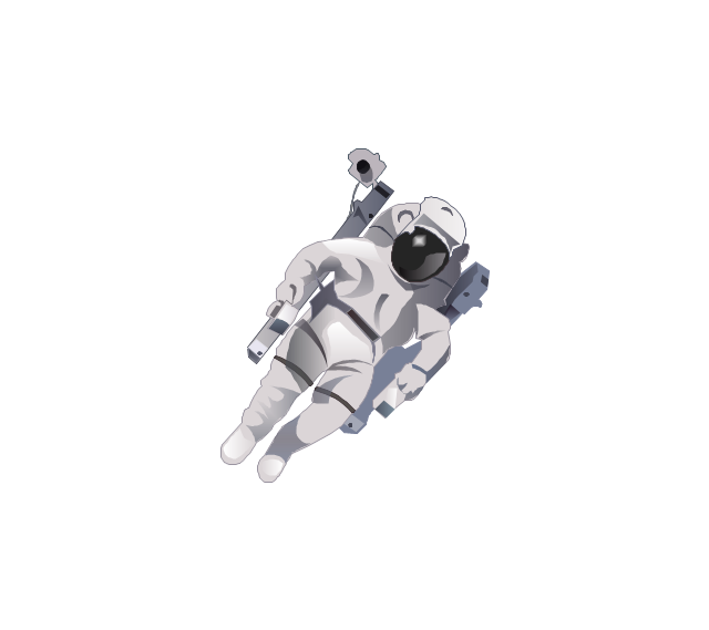
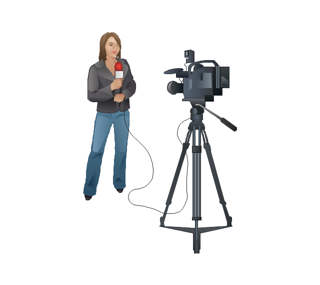
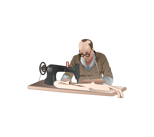
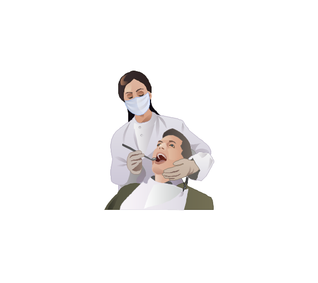
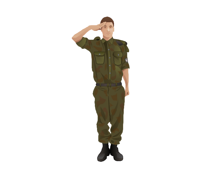
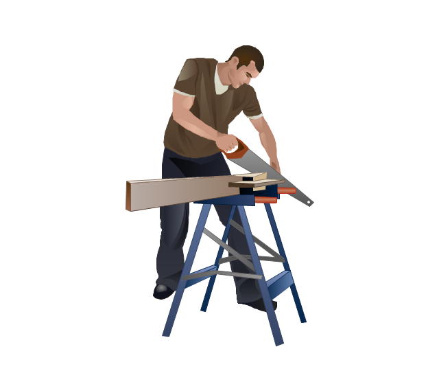
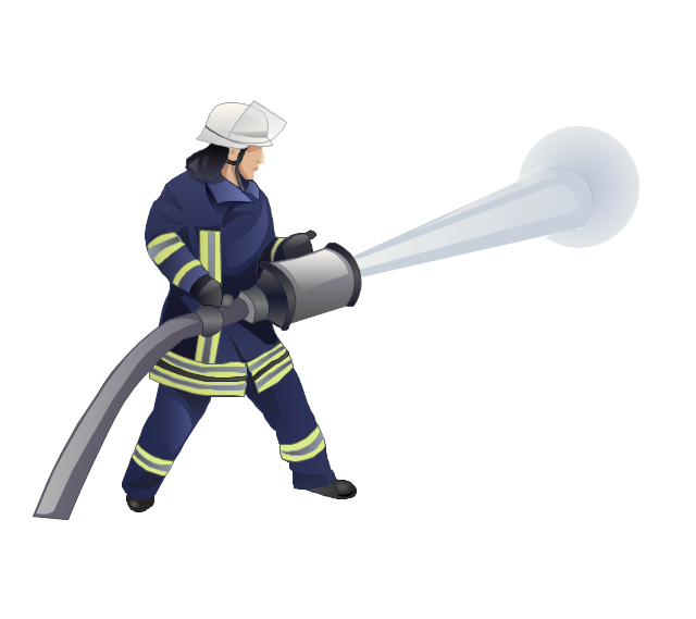
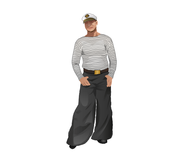
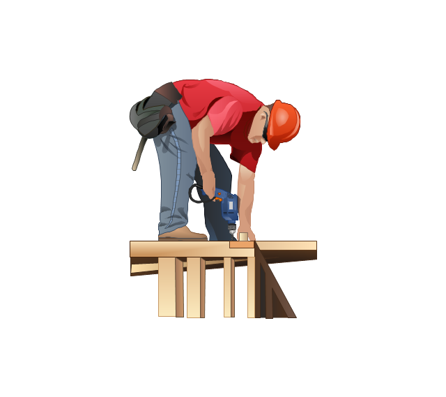
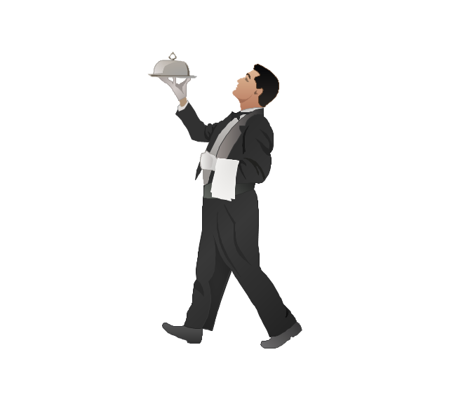
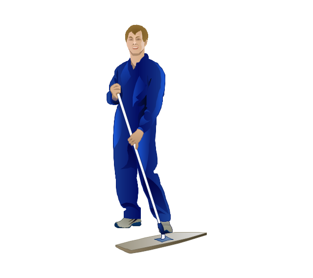
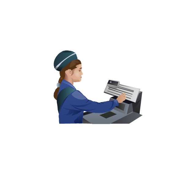
The vector stencils library "Professions" contains 58 people clipart images of different professions you can use in your presentations, illustrations and infographics.
"Electronic clip art is available in several different file formats. It is important for clip art users to understand the differences between file formats so that they can use an appropriate image file and get the resolution and detail results they need.
Clip art file formats are divided into 2 different types: bitmap or vector graphics. ...
In contrast to the grid format of bitmap images, Vector graphics file formats use geometric modeling to describe an image as a series of points, lines, curves, and polygons. Because the image is described using geometric data instead of fixed pixels, the image can be scaled to any size while retaining "resolution independence", meaning that the image can be printed at the highest resolution a printer supports, resulting in a clear, crisp image. Vector file formats are usually superior in resolution and ease of editing as compared to bitmap file formats, but are not as widely supported by software and are not well-suited for storing pixel-specific data such as scanned photographs. In the early years of electronic clip art, vector illustrations were limited to simple line art representations." [Clip art. Wikipedia]
The clip art example "Professions - Vector stencils library" was created using the ConceptDraw PRO diagramming and vector drawing software extended with the People solution from the Illustration area of ConceptDraw Solution Park.
www.conceptdraw.com/ solution-park/ illustrations-people
Builder 1

System administrator
Worker of conveyor
Clerk 1

Clerk 2

Student 2
Student 3

Student 1

Dispatcher 1

Accountant

Gardener

Lawyer

Jurist

Judge
Consultant

Manager

Director

Programmer

Architect

Pilot

Policeman

Secretary

Security officer
Clerk 3

Musician
Presenter

Athlete
Artist
Announcer

Photographer

Hairdresser
Florist
Spaceman
Engineer

Reporter
Tailor
Dispatcher 2

Biologist

Chemist

Dentist
Priest

Soldier
Doctor

Driver

Carpenter
Fireman
Seaman
Builder 2
Postman

Miner

Waiter
Cleaner
Cashier
Shop assistant
Cook

Flight attendant

Teacher

Hall porter

- Welded joints types | Butt weld geometry | Elements location of a ...
- T Welded Joint Wikipedia
- Welding symbols | Design elements - Welding | Welding - Vector ...
- Butt weld geometry | Welded joints types | Welding symbols | Draw ...
- T Joint Diagram Electrical
- Welded joints types | Butt weld geometry | Welding symbols | Types ...
- Butt weld geometry | Welding symbols | Welded joints types ...
- Butt weld geometry | Mechanical Engineering | Welded joints types ...
- Design elements - Pipes (part 1) | Welding symbols | Pipes 2 ...
- Butt weld geometry | Welding symbols | Welded joints types | Lap ...
- Draw A Bevel Joint Symbol
- Butt weld geometry | Welding symbols | Welded joints types | Weld ...
- Welded joints types | Butt weld geometry | Design elements ...
- Welding symbols | Elements location of a welding symbol | Design ...
- Welding symbols | Design elements - Pipes (part 1) | Mechanical ...
- Flange Joints Eng Drawing
- Welded joints types | Mechanical Engineering | Butt weld geometry ...
- Butt weld geometry | Welded joints types | Design elements ...
- Welding symbols | Plumbing and Piping Plans | Design elements ...
- Cross Joint In Engineering Drawing