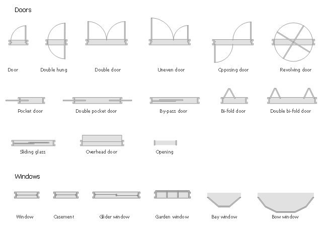
The design elements library Doors contains 69 symbols of doors.
The design elements library Windows contains 34 symbols of windows and casements.
"A door is an opening or closing structure used to block off an entrance, typically consisting of an interior side that faces the inside of a space and an exterior side that faces the outside of that space. While in some cases the interior side of a door may match its exterior side, in other cases there are sharp contrasts between the two sides, such as in the case of the vehicle door. In addition, doors typically consist of a panel that swings on hinges or that slides or spins inside of a space." [Door. Wikipedia]
"A window is an opening in a wall, door or vehicle that allows the passage of light and, if not closed or sealed, air and sound. Modern windows are usually glazed or covered in some other transparent or translucent material. Windows are held in place by frames. Many glazed windows may be opened, to allow ventilation, or closed, to exclude inclement weather." [Window. Wikipedia]
Use the shapes libraries Doors and Windows to create house plans, home plans, floor plan layouts and home designs using the ConceptDraw PRO diagramming and vector drawing software.
The vector stencils libraries Doors and Windows are provided by the Floor Plans solution from the Building Plans area of ConceptDraw Solution Park.
This HVAC plan sample shows the air handler layout on the floor plan.
"An air handler, or air handling unit (often abbreviated to AHU), is a device used to condition and circulate air as part of a heating, ventilating, and air-conditioning (HVAC) system. An air handler is usually a large metal box containing a blower, heating or cooling elements, filter racks or chambers, sound attenuators, and dampers. Air handlers usually connect to a ductwork ventilation system that distributes the conditioned air through the building and returns it to the AHU. Sometimes AHUs discharge (supply) and admit (return) air directly to and from the space served without ductwork.
Small air handlers, for local use, are called terminal units, and may only include an air filter, coil, and blower; these simple terminal units are called blower coils or fan coil units. A larger air handler that conditions 100% outside air, and no recirculated air, is known as a makeup air unit (MAU). An air handler designed for outdoor use, typically on roofs, is known as a packaged unit (PU) or rooftop unit (RTU)." [Air handler. Wikipedia]
The floor plan example "Air handler - HVAC plan" was created using the ConceptDraw DIAGRAM diagramming and vector drawing software extended with the HVAC Plans solution from the Building Plans area of ConceptDraw Solution Park.
Floor plan

Room planning with ConceptDraw DIAGRAM

Create Floor Plans Easily with ConceptDraw DIAGRAM


Use this template to develop the home layouts, space plans, interior design, kitchen and bathroom design, architectural and construction documents using ConceptDraw PRO diagramming and vector drawing software.
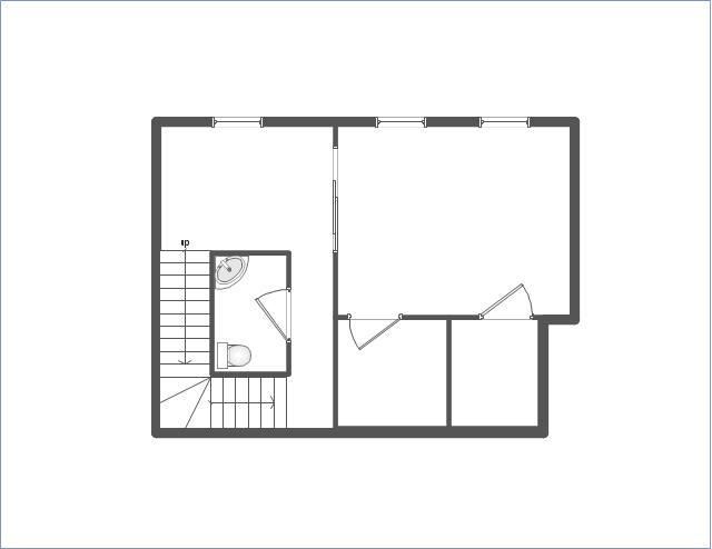
"A floor plan is the most fundamental architectural diagram, a view from above showing the arrangement of spaces in building in the same way as a map, but showing the arrangement at a particular level of a building. Technically it is a horizontal section cut through a building (conventionally at three feet / one metre above floor level), showing walls, windows and door openings and other features at that level. The plan view includes anything that could be seen below that level: the floor, stairs (but only up to the plan level), fittings and sometimes furniture. Objects above the plan level (e.g. beams overhead) can be indicated as dotted lines." [Architectural drawing. Wikipedia]
The Home floor plan template is included in the Floor Plans solution from the Building Plans area of ConceptDraw Solution Park.
www.conceptdraw.com/ solution-park/ floor-plans
How to create Cafe Floor Plan Design
This HVAC floor plan sample illustrates the temperature sensors of air handler digital thermostat control.
"A thermostat is a component of a control system which senses the temperature of a system so that the system's temperature is maintained near a desired setpoint. The thermostat does this by switching heating or cooling devices on or off, or regulating the flow of a heat transfer fluid as needed, to maintain the correct temperature. The name is derived from the Greek words thermos "hot" and statos "a standing".
A thermostat may be a control unit for a heating or cooling system or a component part of a heater or air conditioner. Thermostats can be constructed in many ways and may use a variety of sensors to measure the temperature. The output of the sensor then controls the heating or cooling apparatus. A thermostat may switch on and off at temperatures either side of the setpoint the extent of the difference is known as hysteresis and prevents too frequent switching of the controlled equipment." [Thermostat. Wikipedia]
The HVAC plan example "Digital unit ventilator control" was created using the ConceptDraw DIAGRAM diagramming and vector drawing software extended with the HVAC Plans solution from the Building Plans area of ConceptDraw Solution Park.
HVAC floor plan

HelpDesk
How to Create a Plant Layout Design

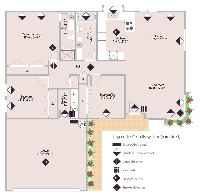
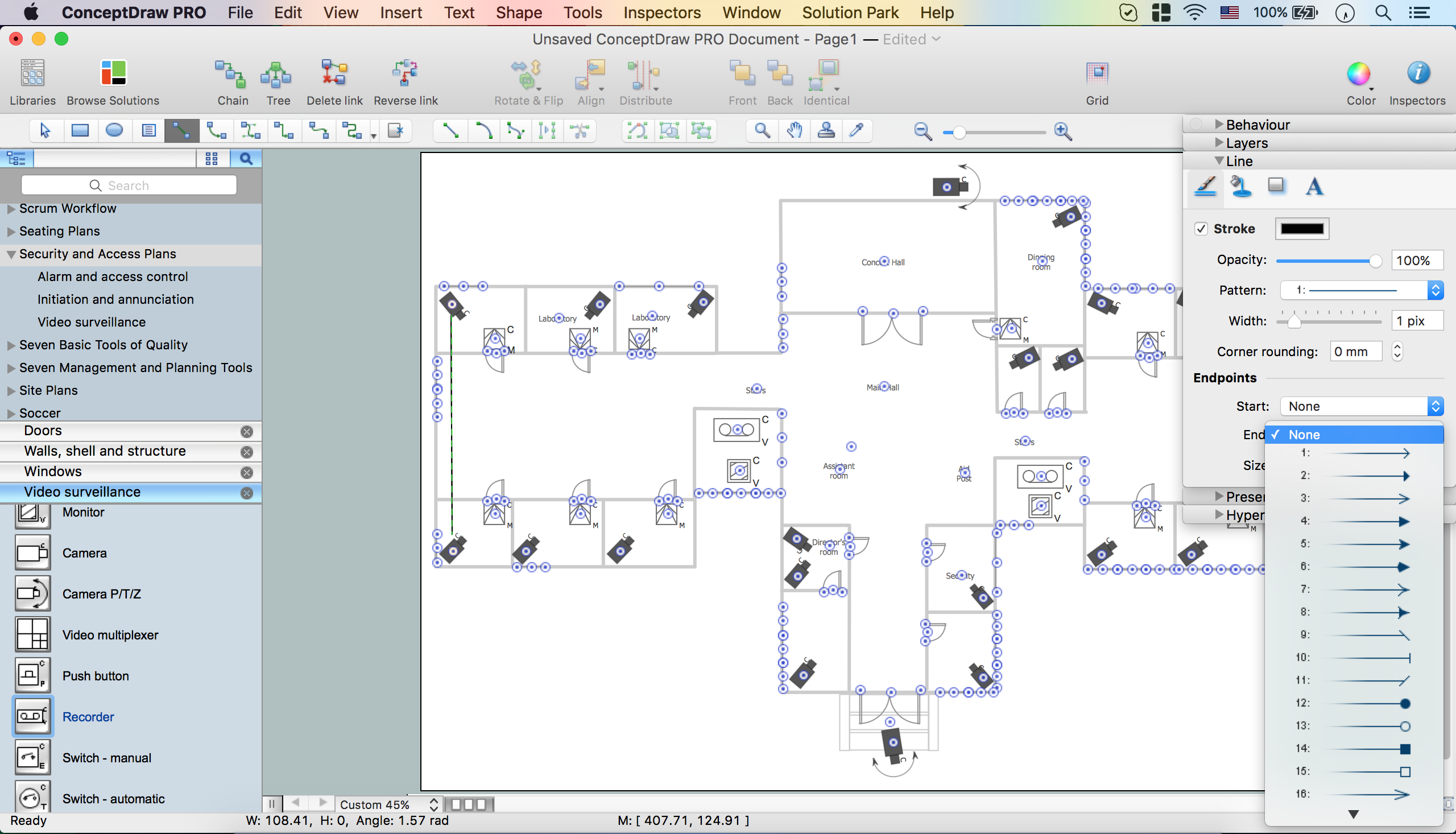
This sample was created on the base of the floor plan with security system device symbols from the website of the California State University, Sacramento. [imet.csus.edu/ imet1/ denyer/ mhs_ denyer/ drafting/ arch_ ch_ 31/ 31-28.jpg]
Legend for the security system hardware includes distribution panel, window-door contact, sonic detector, key pads, heat detectors, smoke detectors.
The example "Security system floor plan" was created using the ConceptDraw PRO diagramming and vector drawing software extended with the Security and Access Plans solution from the Building Plans area of ConceptDraw Solution Park.
Security system floor plan
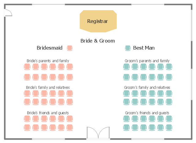
This seating plan sample shows the seat layout at the wedding ceremony.
"A wedding is a ceremony where people are united in marriage. Wedding traditions and customs vary greatly between cultures, ethnic groups, religions, countries, and social classes. Most wedding ceremonies involve an exchange of wedding vows by the couple, presentation of a gift (offering, ring(s), symbolic item, flowers, money), and a public proclamation of marriage by an authority figure or leader. Special wedding garments are often worn, and the ceremony is sometimes followed by a wedding reception. Music, poetry, prayers or readings from religious texts or literature are also commonly incorporated into the ceremony." [Wedding. Wikipedia]
The seat layout example "Wedding ceremony seating plan" was created using the ConceptDraw PRO diagramming and vector drawing software extended with the Seating Plans solution from the Building Plans area of ConceptDraw Solution Park.
Seat layout
Interior Design. Office Layout Plan Design Element

Mini Hotel Floor Plan. Floor Plan Examples

 Floor Plans
Construction, repair and remodeling of the home, flat, office, or any other building or premise begins with the development of detailed building plan and floor plans. Correct and quick visualization of the building ideas is important for further construction of any building.
How To use Appliances Symbols for Building Plan

How To Create CCTV Network Diagram
- Door Window Plan Sign
- Rolling Door And Window Plan
- Floor Plans | Fire and Emergency Plans | Physics | Door Window ...
- Design elements - Doors and windows | Building Plans with ...
- Design elements - Doors and windows | Plumbing and Piping Plans ...
- Design elements - Doors and windows | Coffee shop floor plan ...
- Doors Vector Plan
- Look Of Door Window Ventileter In Single Line Plan
- House Plan Door Window Details
- How To Represent A Double Door In A House Plan
- Security system floor plan | Design elements - Doors and windows ...
- Door And Windows Plans
- Design elements - Doors and windows | How to Get Images for ...
- Design elements - Doors and windows
- Design elements - Doors and windows | Air handler- HVAC plan ...
- Floor Plan Symbol For Slding Glass Doors
- Cafe electrical floor plan | Symbol Of Double Hung Door
- Security system floor plan | Windows 8 User Interface | How to Plan ...
- Door Openings Plan Section Drawing
- Design elements - Doors and windows | How To use Appliances ...