The vector stencils library "Semiconductor diodes" contains 24 symbols of semiconductor diodes for drawing electronic schematics and circuit diagrams.
"In electronics, a diode is a two-terminal electronic component with asymmetric conductance; it has low (ideally zero) resistance to current in one direction, and high (ideally infinite) resistance in the other. A semiconductor diode, the most common type today, is a crystalline piece of semiconductor material with a p–n junction connected to two electrical terminals. A vacuum tube diode has two electrodes, a plate (anode) and a heated cathode. Semiconductor diodes were the first semiconductor electronic devices. ...
Today, most diodes are made of silicon, but other semiconductors such as selenium or germanium are sometimes used." [Diode. Wikipedia]
The shapes example "Design elements - Semiconductor diodes" was drawn using the ConceptDraw PRO diagramming and vector drawing software extended with the Electrical Engineering solution from the Engineering area of ConceptDraw Solution Park.
Semiconductor diode symbols

Electrical Symbols — Semiconductor Diodes

The vector stencils library "Semiconductor diodes" contains 24 symbols of semiconductor diodes.
Use these shapes for drawing electronic schematics and circuit diagrams in the ConceptDraw PRO diagramming and vector drawing software extended with the Electrical Engineering solution from the Engineering area of ConceptDraw Solution Park.
www.conceptdraw.com/ solution-park/ engineering-electrical
Use these shapes for drawing electronic schematics and circuit diagrams in the ConceptDraw PRO diagramming and vector drawing software extended with the Electrical Engineering solution from the Engineering area of ConceptDraw Solution Park.
www.conceptdraw.com/ solution-park/ engineering-electrical
Diode, env
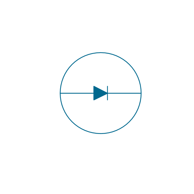
Diode

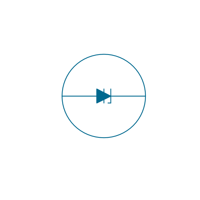
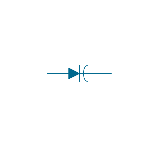
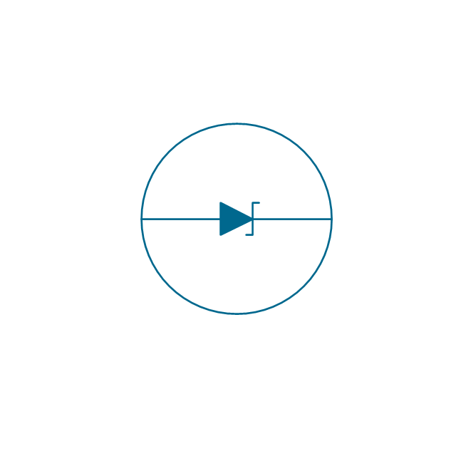
Diode, reverse blocking, env

Diode, reverse blocking

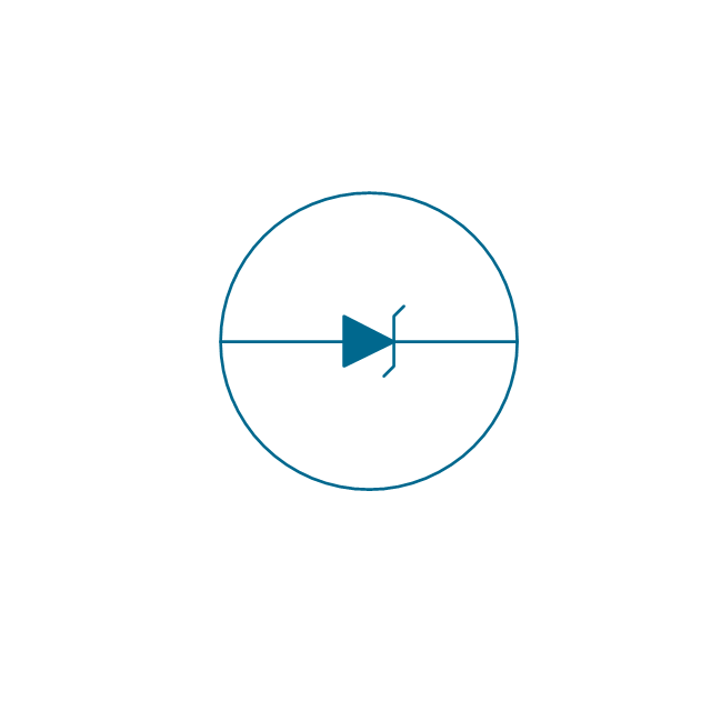
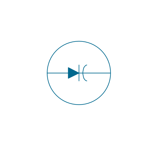
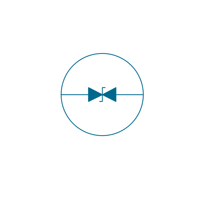
Diode, reverse conducting, env
Diode, reverse conducting

Tunnel diode, env

Tunnel diode

Zener diode, env
Zener diode

Backward diode, env
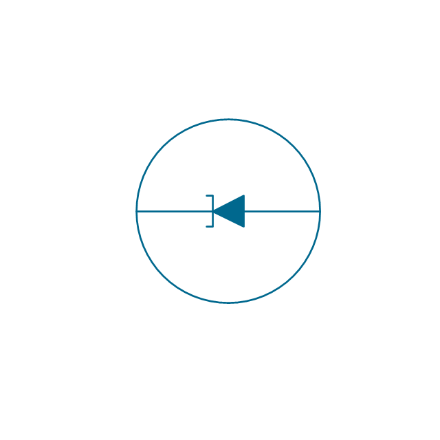
Backward diode

Varactor, env
Varactor
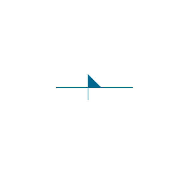
Four layer diode, env
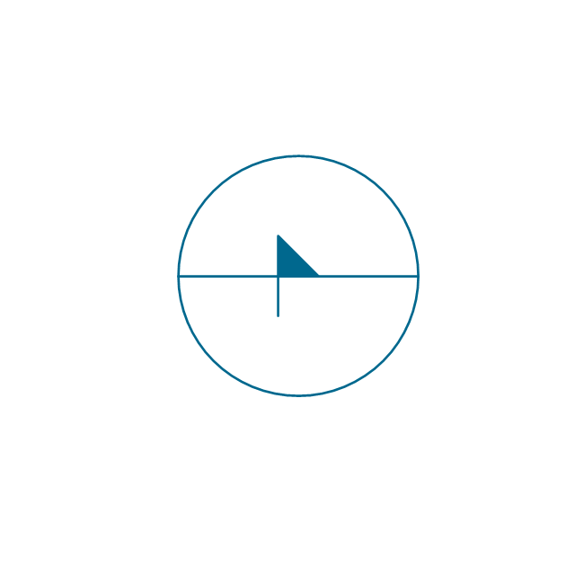
Four layer diode
LED, env
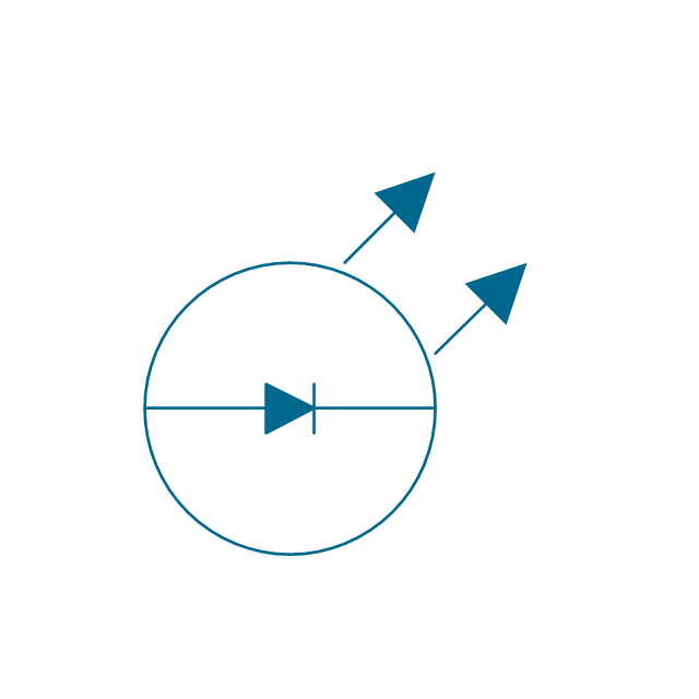
LED
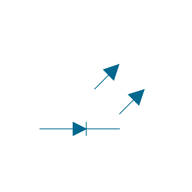
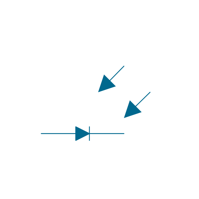
Photo-diode, env
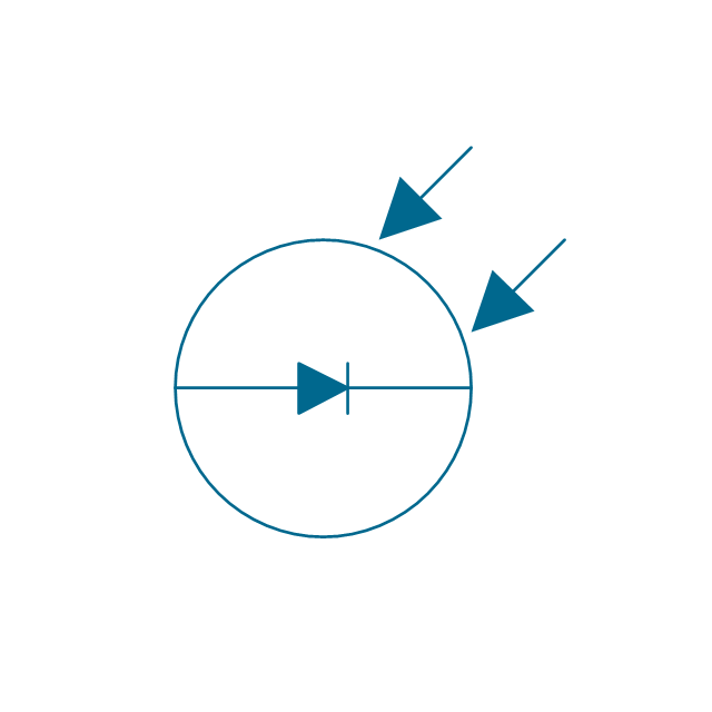
Photo-diode
Breakdown diode, uni-directional, env
Breakdown diode, uni-directional

Breakdown diode, bi-directional, env
Breakdown diode, bi-directional

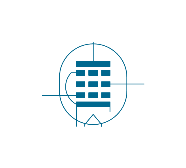
The vector stencils library "Electron tubes" contains 36 element symbols of electron tubes.
Use it for drawing electrical schematics and electronic circuit diagrams in the ConceptDraw PRO diagramming and vector drawing software extended with the Electrical Engineering solution from the Engineering area of ConceptDraw Solution Park.
www.conceptdraw.com/ solution-park/ engineering-electrical
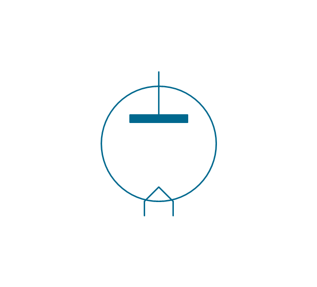
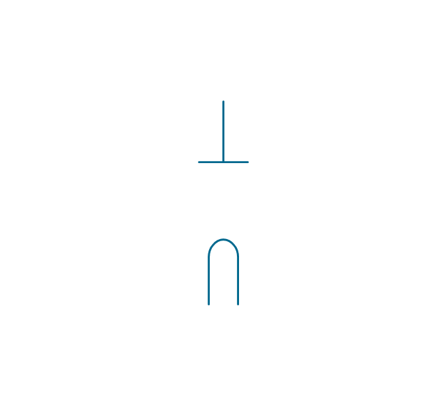
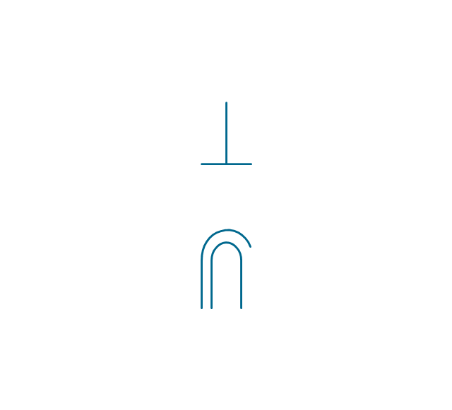
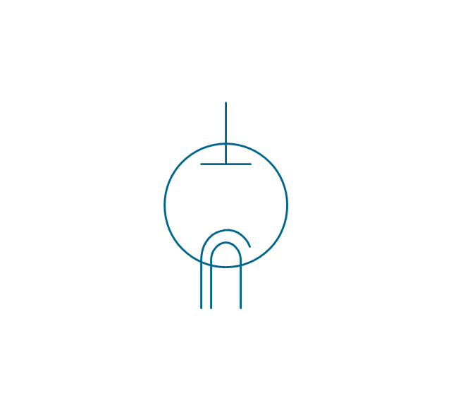
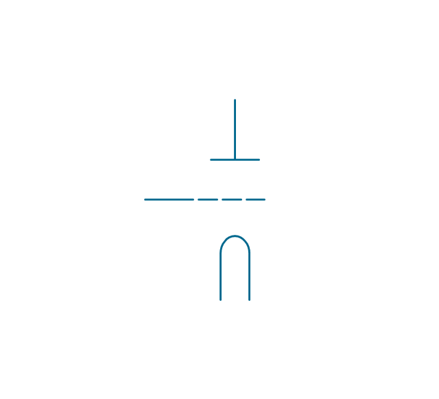
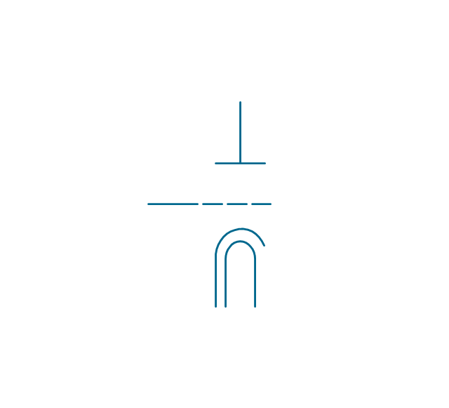
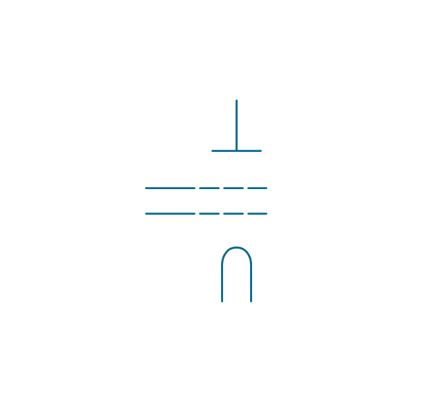
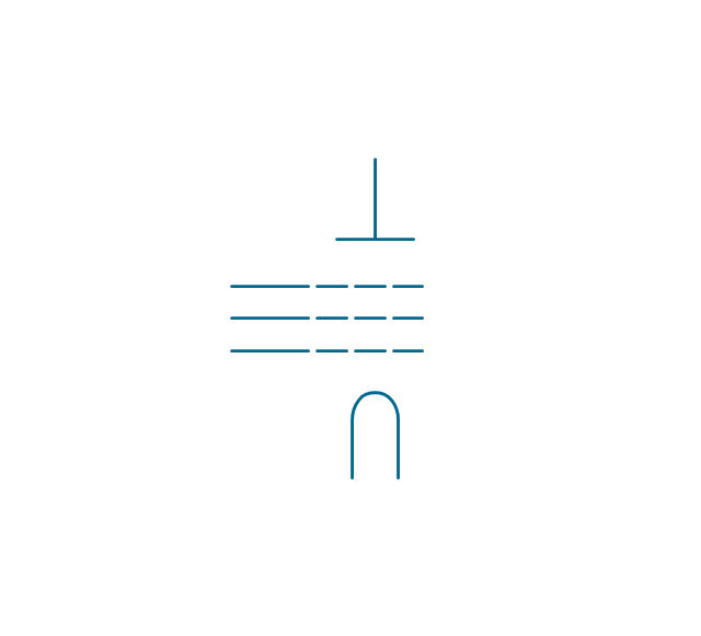
Diode, directly heated
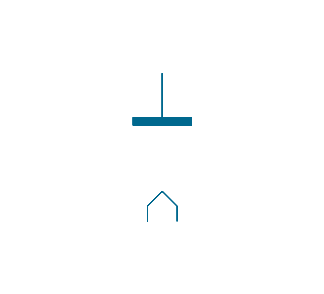
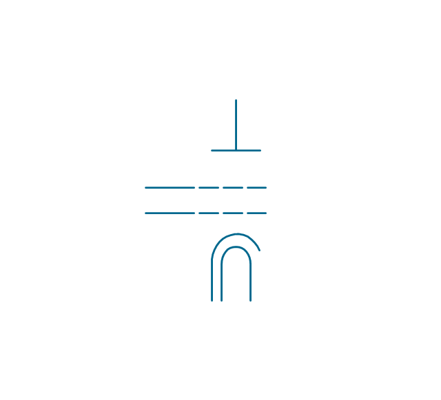
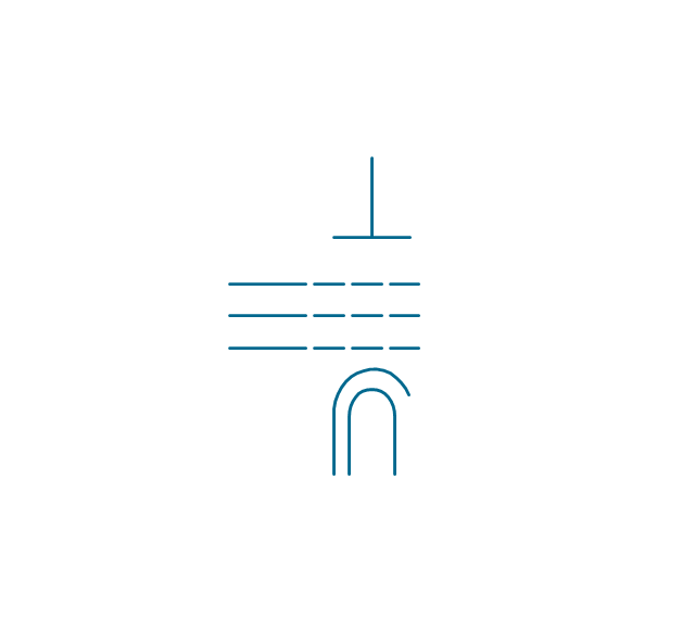
Diode, indirectly heated
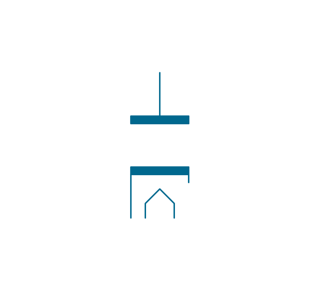
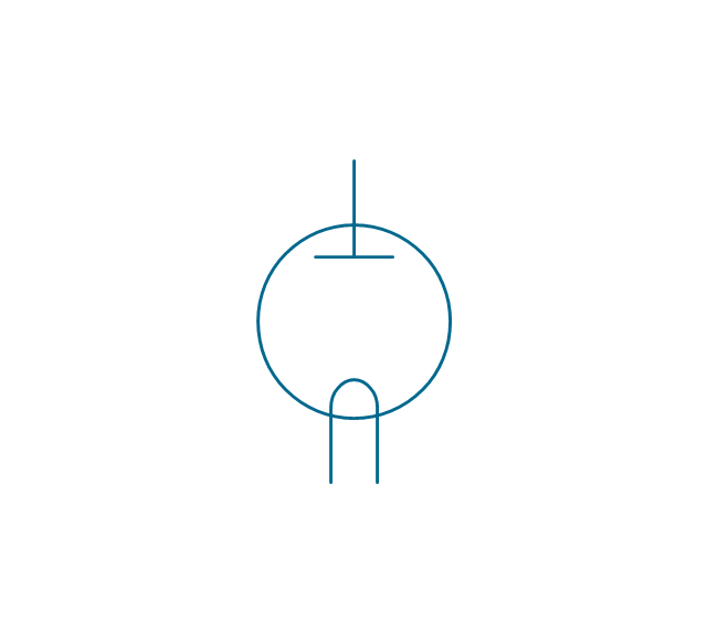
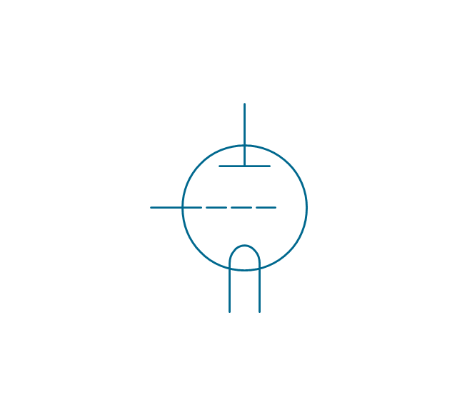
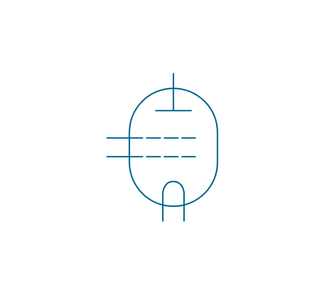
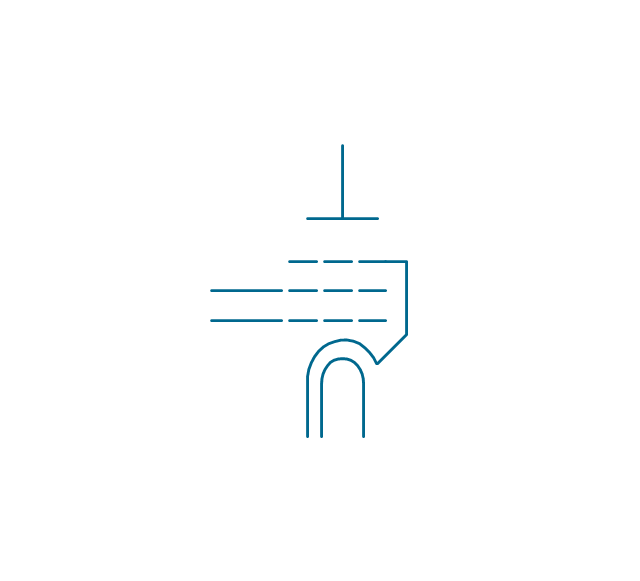
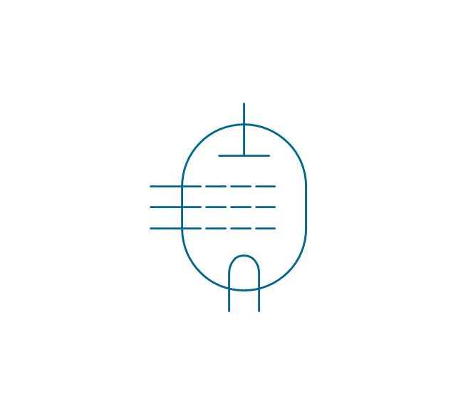
Diode, envelope, direct. heated
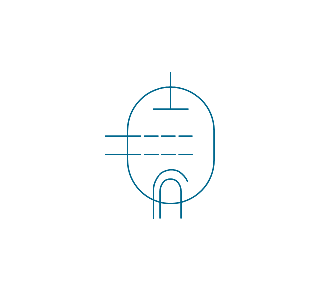
Diode, envelope, indirect. heated
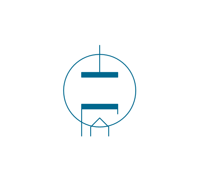
Triode, directly heated
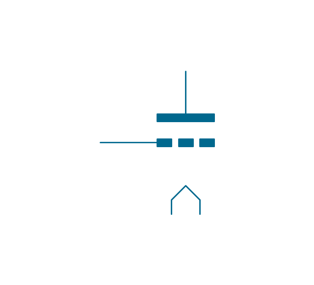
Triode, indirectly heated
Triode, envelope, direct. heated
Triode, envelope, indirect. heated
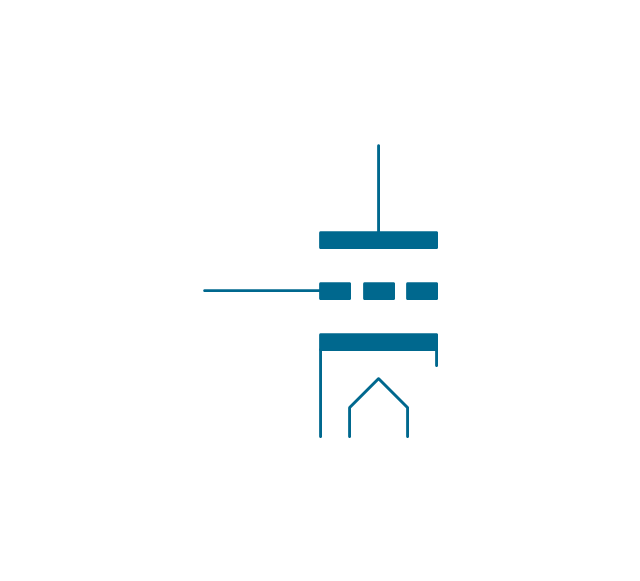
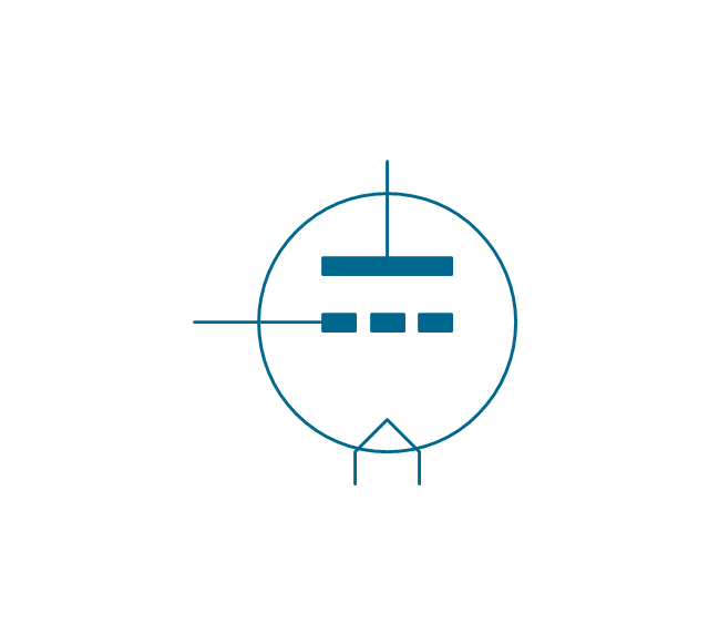
Tetrode, directly heated
Tetrode, indirectly heated

Tetrode, envelope, direct. heated

Tetrode, envelope, indirect. heated
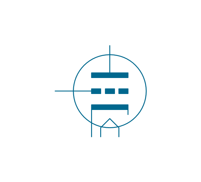
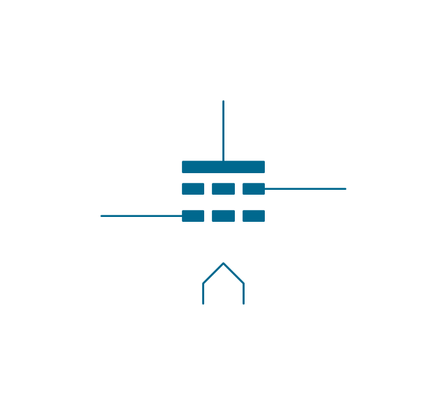
Pentode, directly heated

Pentode, indirectly heated, external connection
Pentode, indirectly heated, internal connection
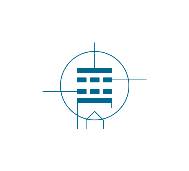
Pentode, envelope, direct. heated
Pentode, envelope, indirect. heated, external connection
Pentode, envelope, indirect. heated, internal connection
Diode, directly heated 2
Diode, indirectly heated 2
Diode, envelope, direct. heated 2
Diode, envelope, indirect. heated 2
Triode, directly heated 2
Triode, indirectly heated 2
Triode, envelope, direct. heated 2
Triode, envelope, indirect. heated 2

Tetrode, directly heated 2
Tetrode, indirectly heated 2
Tetrode, envelope, direct. heated 2
Tetrode, envelope, indirect. heated 2
Pentode, directly heated 2
Pentode, indirectly heated, external connection 2
Pentode, indirectly heated, internal connection 2
Pentode, envelope, direct. heated 2
Pentode, envelope, indirect. heated, external connection 2

Pentode, envelope, indirect. heated, internal connection 2
Electrical Symbols — Electron Tubes

The vector stencils library "Logic gate diagram" contains 17 element symbols for drawing the logic gate diagrams.
"To build a functionally complete logic system, relays, valves (vacuum tubes), or transistors can be used. The simplest family of logic gates using bipolar transistors is called resistor-transistor logic (RTL). Unlike simple diode logic gates (which do not have a gain element), RTL gates can be cascaded indefinitely to produce more complex logic functions. RTL gates were used in early integrated circuits. For higher speed and better density, the resistors used in RTL were replaced by diodes resulting in diode-transistor logic (DTL). Transistor-transistor logic (TTL) then supplanted DTL. As integrated circuits became more complex, bipolar transistors were replaced with smaller field-effect transistors (MOSFETs); see PMOS and NMOS. To reduce power consumption still further, most contemporary chip implementations of digital systems now use CMOS logic. CMOS uses complementary (both n-channel and p-channel) MOSFET devices to achieve a high speed with low power dissipation." [Logic gate. Wikipedia]
The symbols example "Design elements - Logic gate diagram" was drawn using the ConceptDraw PRO diagramming and vector drawing software extended with the Electrical Engineering solution from the Engineering area of ConceptDraw Solution Park.
Logic gate symbols

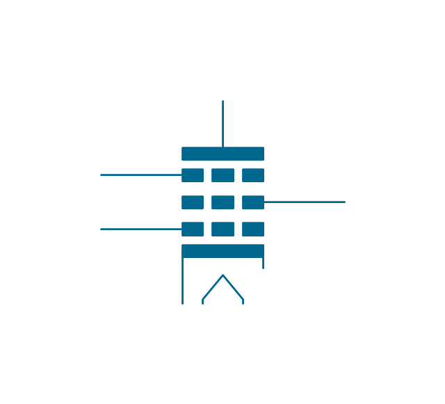
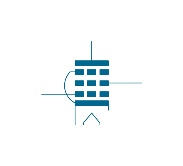
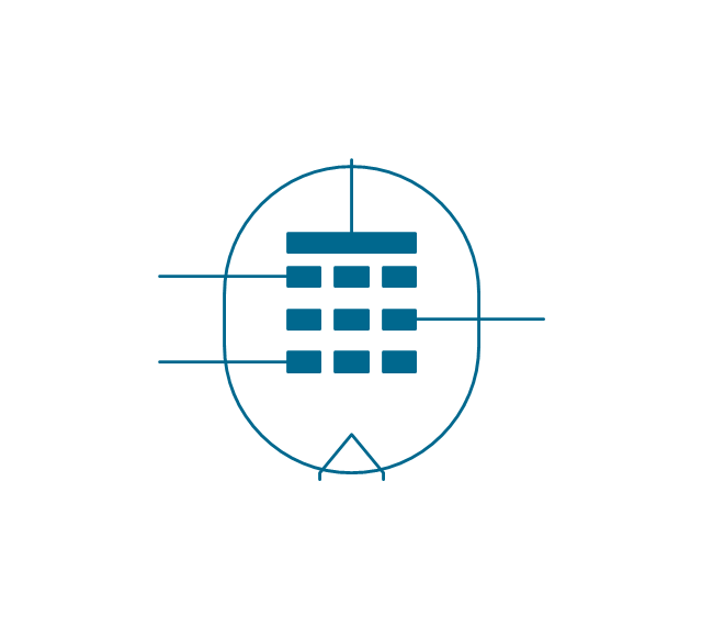
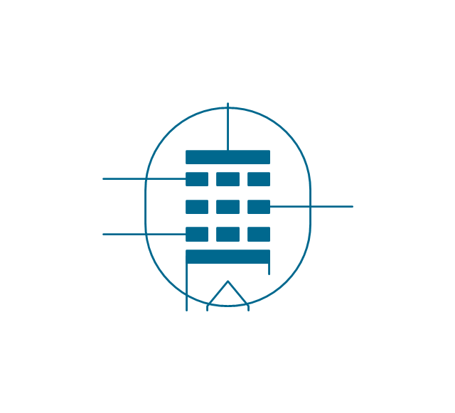
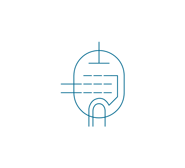
The vector stencils library "Design elements - Electron tubes" contains 36 element symbols of electron tubes.
Use it for drawing electrical schematics and electronic circuit diagrams.
"One classification of vacuum tubes is by the number of active electrodes, (neglecting the filament or heater). A device with two active elements is a diode, usually used for rectification. Devices with three elements are triodes used for amplification and switching. Additional electrodes create tetrodes, pentodes, and so forth, which have multiple additional functions made possible by the additional controllable electrodes.
Other classifications are:
(1) by frequency range (audio, radio, VHF, UHF, microwave),
(2) by power rating (small-signal, audio power, high-power radio transmitting),
(3) by design (e.g., sharp- versus remote-cutoff in some pentodes),
(4) by application (receiving tubes, transmitting tubes, amplifying or switching, rectification, mixing),
(5) special qualities (long life, very low microphonic and low noise audio amplification, and so on).
Multiple classifications may apply to a device; for example similar dual triodes can be used for audio preamplification and as flip-flops in computers, although linearity is important in the former case and long life in the latter.
Tubes have different functions, such as cathode ray tubes which create a beam of electrons for display purposes (such as the television picture tube) in addition to more specialized functions such as electron microscopy and electron beam lithography. X-ray tubes are also vacuum tubes. Phototubes and photomultipliers rely on electron flow through a vacuum, though in those cases electron emission from the cathode depends on energy from photons rather than thermionic emission." [Vacuum tube. Wikipedia]
The symbols example "Design elements - Electron tubes" was drawn using the ConceptDraw PRO diagramming and vector drawing software extended with the Electrical Engineering solution from the Engineering area of ConceptDraw Solution Park.
Vacuum tubes

Electrical Symbols, Electrical Diagram Symbols

Electrical Symbols — Semiconductor

Electrical Drawing Software and Electrical Symbols

- Electrical Drawing Software and Electrical Symbols | Design ...
- Semiconductor diodes - Vector stencils library | Design elements ...
- Electrical Symbols — Semiconductor Diodes | Design elements ...
- Design elements - Semiconductor diodes | Semiconductors - Vector ...
- Semiconductors - Vector stencils library | Semiconductor diodes ...
- Electrical Symbols, Electrical Diagram Symbols | Electrical Drawing ...
- Design elements - Semiconductor diodes | Semiconductor diodes ...
- Design elements - Semiconductor diodes | Types Of Diode Simble
- Design elements - Semiconductor diodes | Design elements - Delay ...
- Circuit diagram - EL 34 schematics | Design elements - Electron ...