 Plant Layout Plans
This solution extends ConceptDraw PRO v.9.5 plant layout software (or later) with process plant layout and piping design samples, templates and libraries of vector stencils for drawing Plant Layout plans. Use it to develop plant layouts, power plant desig
 Engineering
This solution extends ConceptDraw PRO v9.4 with the ability to visualize industrial systems in electronics, electrical, chemical, process, and mechanical engineering.
HelpDesk
How to Draw a Chemical Process Flow Diagram
Process Flow Diagram widely used in modeling of processes in the chemical industry. A Chemical Process Flow diagram (PFD) is a specialized type of flowchart. With the help of Chemical Process Flow Diagram engineers can easily specify the general scheme of the processes and chemical plant equipment. Chemical Process Flow Diagram displays the real scheme of the chemical process, the relationship between the equipment and the technical characteristics of the process. Chemical Process Flow Diagram illustrates the connections between the basic equipment as well as the overall structure of pipelines and other supporting equipment. The purpose of the PFD is to build the image of the basic idea of the chemical process. ConceptDraw PRO together with its Chemical and Process Engineering solution delivers the possibility to design Chemical Process Flow diagrams. It is designed for chemical industry engineers and designers.HelpDesk
How to Draw a Block Diagram in ConceptDraw PRO
Block diagram is a simple chart that use blocks to show some elements or activities, and connectors that show the relationship between neighboring blocks. They are commonly simple, giving an overview of a process without necessarily going into the specifics of implementation. Block diagrams are commonly used to depict a general description of a system and its activity. A most known sample of a block diagram is a flow chart, used in many types of business as a common method of representing repeated processes. Easy and a simple creation, a number of objects and connectors make the block diagram a many-sided tool for various industries. The ability to make block diagrams is delivered by the ConceptDraw Block Diagrams solution.
 ATM UML Diagrams
The ATM UML Diagrams solution lets you create ATM solutions and UML examples. Use ConceptDraw PRO as a UML diagram creator to visualize a banking system.
HelpDesk
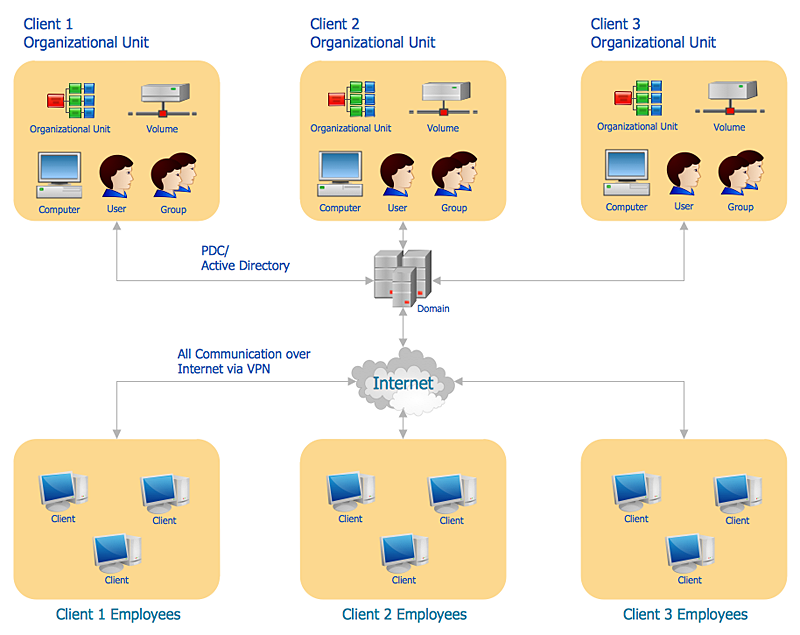
How to Create an Active Directory Diagram in ConceptDraw PRO
Active Directory Service represents a distributed database that contains all the domain objects. The Active Directory domain environment is a single point of authentication and authorization of users and applications across the enterprise. The domain of the organization and deployment of Active Directory Service are exactly the cornerstones of the enterprise IT infrastructure. The logical diagrams of MS Windows Active Directory structure are used to visually support an enterprise IT infastructure planning and management. ConceptDraw PRO allows you to make AD Diagrams quickly and easily using the set of special libraries.- Plant Layout Plans | CAD Drawing Software for Making Mechanic ...
- How To use House Electrical Plan Software | Electrical Drawing ...
- Industrial Building Layout Diagrams
- Process Flowchart | Piping and Instrumentation Diagram Software ...
- Diagram Of An Electrical Drawing Of An Industry
- A Plan Sketch Of Software Industry Building
- Process Flowchart | Piping and Instrumentation Diagram Software ...
- Building Drawing Design Element: Piping Plan | Plumbing and ...
- Factory layout floor plan | Plant Layout Plans | Bar Diagrams for ...
- Plumbing and Piping Plans | How to Create a Residential Plumbing ...
- Plant Layout Plans | ATM UML Diagrams | Hotel Plan . Hotel Plan ...
- Plant Layout Plans | Factory layout floor plan | Emergency Plan ...
- Building Drawing Software for Design Storage and Distribution ...
- How to Create a Residential Plumbing Plan | Piping and ...
- Interior Design Piping Plan - Design Elements | Plumbing and ...
- Building Drawing Design Element: Piping Plan | Piping and ...
- How To Draw Building Plans | Plant Layout Plans | Warehouse with ...
- Electrical Drawing Software | How To use House Electrical Plan ...
- Process Flowchart | Building Drawing Design Element: Piping Plan ...
- Building Drawing Software for Designing Plumbing | Building ...


