UML Activity Diagram

 ATM UML Diagrams
The ATM UML Diagrams solution lets you create ATM solutions and UML examples. Use ConceptDraw PRO as a UML diagram creator to visualize a banking system.
Bank UML Diagram

Bank System

Banking System

 Entity-Relationship Diagram (ERD)
Entity-Relationship Diagram (ERD) solution extends ConceptDraw PRO software with templates, samples and libraries of vector stencils from drawing the ER-diagrams by Chen's and crow’s foot notations.
 Event-driven Process Chain Diagrams
Event-driven Process Chain (EPC) Diagram is a type of flowchart widely used for modeling in business engineering and reengineering, business process improvement, and analysis. EPC method was developed within the Architecture of Integrated Information Systems (ARIS) framework.
HelpDesk
How to Create a Bank ATM Use Case Diagram

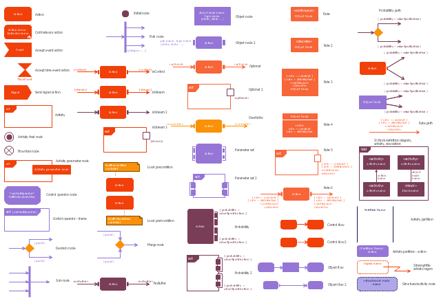
The vector stencils library "Activity diagram" contains 47 symbols.
Use it to design your SysML activity diagrams using ConceptDraw PRO diagramming and vector drawing software.
"Activity diagrams are constructed from a limited number of shapes, connected with arrows. The most important shape types:
- rounded rectangles represent actions;
- diamonds represent decisions;
- bars represent the start (split) or end (join) of concurrent activities;
- a black circle represents the start (initial state) of the workflow;
- an encircled black circle represents the end (final state).
Arrows run from the start towards the end and represent the order in which activities happen." [Activity diagram. Wikipedia]
The SysML shapes example "Design elements - Activity diagram" is included in the SysML solution from the Software Development area of ConceptDraw Solution Park.
SysML activity diagram symbols
 Data Flow Diagrams (DFD)
Data Flow Diagrams solution extends ConceptDraw PRO software with templates, samples and libraries of vector stencils for drawing the data flow diagrams (DFD).
Diagramming Software for Design UML Activity Diagrams
")

 Plant Layout Plans
This solution extends ConceptDraw PRO v.9.5 plant layout software (or later) with process plant layout and piping design samples, templates and libraries of vector stencils for drawing Plant Layout plans. Use it to develop plant layouts, power plant desig
 Business Process Diagrams
Business Process Diagrams solution extends the ConceptDraw PRO BPM software with RapidDraw interface, templates, samples and numerous libraries based on the BPMN 1.2 and BPMN 2.0 standards, which give you the possibility to visualize equally easy simple and complex processes, to design business models, to quickly develop and document in details any business processes on the stages of project’s planning and implementation.
- Design And Develop Use Case Diagram And Activity Diagram For ...
- Activity Diagram For Atm Application
- UML Activity Diagram
- UML activity diagram - Cash withdrawal from ATM | Data Flow ...
- UML Deployment Diagram Example - ATM System | ATM UML ...
- UML activity diagram - Cash withdrawal from ATM | Design elements ...
- UML Activity Diagram | Diagramming Software for Design UML ...
- UML Diagram | Bank UML Diagram | ATM UML Diagrams | Package ...
- UML activity diagram - Cash withdrawal from ATM | ATM UML ...
- ATM UML Diagrams | UML Deployment Diagram Example - ATM ...
- UML Deployment Diagram Example - ATM System | UML Use Case ...
- Activity Diagram Of Atm
- ATM UML Diagrams | UML Deployment Diagram Example - ATM ...
- Package Diagram With Example In Banking System Model
- UML activity diagram
- Activity Diagram For Atm Machine In Software
- Activity Diagram Of Uml For Atm Machine
- Design elements - Bank UML activity diagram | UML activity diagram ...
- UML use case diagram - Banking system
- UML Activity Diagram | ATM UML Diagrams | Event-driven Process ...