The vector stencils library "Telecom equipment" contains 11 hardware clipart icons of telecommunication devices for drawing computer network diagrams and equipment layouts.
"In telecommunication, a communications system is a collection of individual communications networks, transmission systems, relay stations, tributary stations, and data terminal equipment (DTE) usually capable of interconnection and interoperation to form an integrated whole. The components of a communications system serve a common purpose, are technically compatible, use common procedures, respond to controls, and operate in union. Telecommunications is a method of communication." [Communications system. Wikipedia]
"A basic telecommunication system consists of three primary units that are always present in some form: (1) A transmitter that takes information and converts it to a signal. (2) A transmission medium, also called the "physical channel" that carries the signal. ... (3) A receiver that takes the signal from the channel and converts it back into usable information." [Telecommunication. Wikipedia]
The clip art example "Telecom equipment - Vector stencils library" was created using the ConceptDraw PRO diagramming and vector drawing software extended with the Telecommunication Network Diagrams solution from the Computer and Networks area of ConceptDraw Solution Park.
Andrew multiband high / low power splitter

Andrew multi-band indoor omnidirectional antenna

Panel sector directional antenna

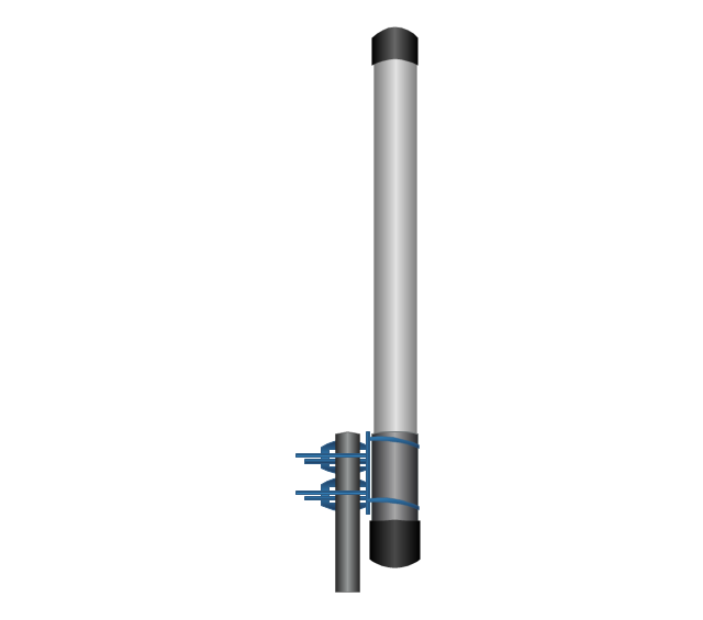
Omni directional antenna
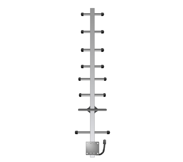
Yagi directional antenna
Yagi integrated downconverter

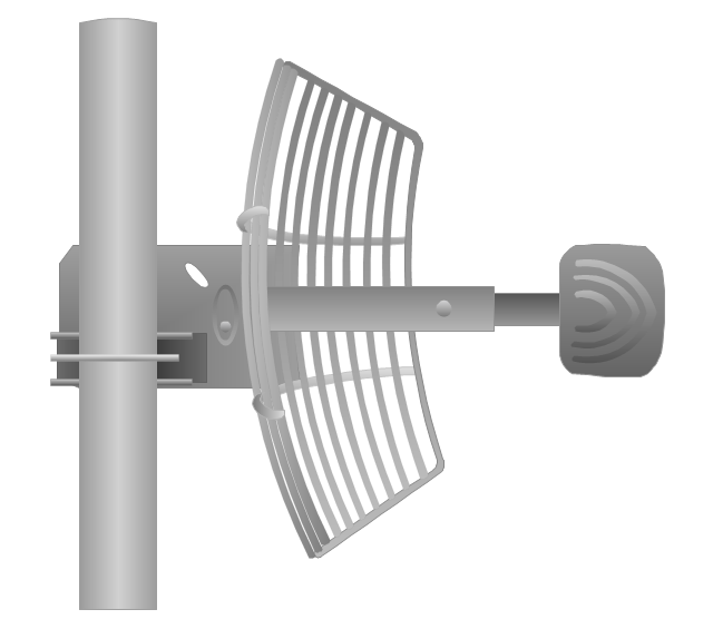
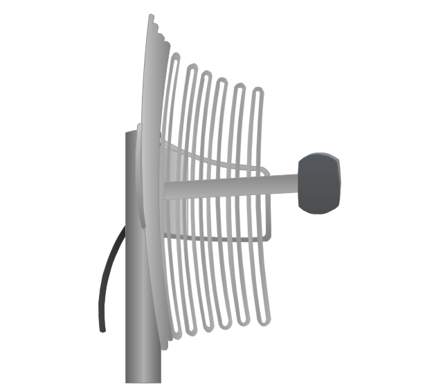
Grid antenna
Loop antenna
FireTide HotPort® 6000 wireless mesh nodes
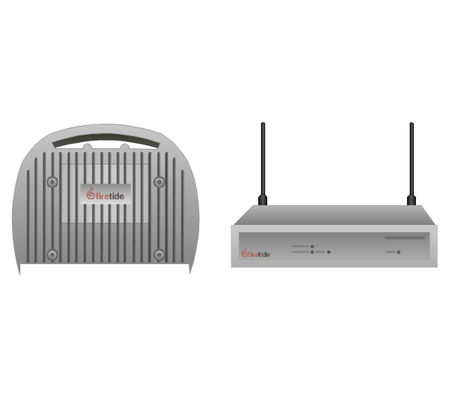
FireTide HotPoint® wireless access point
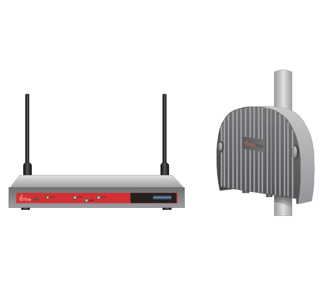
FireTide HotClient Customer Premises Equipment (CPE)
-telecom-equipment---vector-stencils-library.png--diagram-flowchart-example.png)
The vector stencils library "Telecom equipment" contains 11 hardware clipart icons of telecommunication devices for drawing computer network diagrams and equipment layouts.
"In telecommunication, a communications system is a collection of individual communications networks, transmission systems, relay stations, tributary stations, and data terminal equipment (DTE) usually capable of interconnection and interoperation to form an integrated whole. The components of a communications system serve a common purpose, are technically compatible, use common procedures, respond to controls, and operate in union. Telecommunications is a method of communication." [Communications system. Wikipedia]
"A basic telecommunication system consists of three primary units that are always present in some form: (1) A transmitter that takes information and converts it to a signal. (2) A transmission medium, also called the "physical channel" that carries the signal. ... (3) A receiver that takes the signal from the channel and converts it back into usable information." [Telecommunication. Wikipedia]
The clip art example "Telecom equipment - Vector stencils library" was created using the ConceptDraw PRO diagramming and vector drawing software extended with the Telecommunication Network Diagrams solution from the Computer and Networks area of ConceptDraw Solution Park.
"In telecommunication, a communications system is a collection of individual communications networks, transmission systems, relay stations, tributary stations, and data terminal equipment (DTE) usually capable of interconnection and interoperation to form an integrated whole. The components of a communications system serve a common purpose, are technically compatible, use common procedures, respond to controls, and operate in union. Telecommunications is a method of communication." [Communications system. Wikipedia]
"A basic telecommunication system consists of three primary units that are always present in some form: (1) A transmitter that takes information and converts it to a signal. (2) A transmission medium, also called the "physical channel" that carries the signal. ... (3) A receiver that takes the signal from the channel and converts it back into usable information." [Telecommunication. Wikipedia]
The clip art example "Telecom equipment - Vector stencils library" was created using the ConceptDraw PRO diagramming and vector drawing software extended with the Telecommunication Network Diagrams solution from the Computer and Networks area of ConceptDraw Solution Park.
Andrew multiband high / low power splitter
Andrew multi-band indoor omnidirectional antenna
Panel sector directional antenna
Omni directional antenna
Yagi directional antenna
Yagi integrated downconverter
Grid antenna
Loop antenna
FireTide HotPort® 6000 wireless mesh nodes
FireTide HotPoint® wireless access point
FireTide HotClient Customer Premises Equipment (CPE)
The vector stencils library "Motorola" contains 10 clipart images of Motorola telecom devices for drawing computer network diagrams and telecommunication equipment layouts.
"Motorola Solutions, Inc. is an American data communications and telecommunications equipment provider that succeeded Motorola Inc., following the spinoff of the mobile phones division into Motorola Mobility in 2011." [Motorola Solutions. Wikipedia]
"Motorola designed and sold wireless network infrastructure equipment such as cellular transmission base stations and signal amplifiers. Motorola's home and broadcast network products included set-top boxes, digital video recorders, and network equipment used to enable video broadcasting, computer telephony, and high-definition television. Its business and government customers consisted mainly of wireless voice and broadband systems (used to build private networks), and, public safety communications systems like Astro and Dimetra." [Motorola. Wikipedia]
The clip art example "Motorola - Vector stencils library" was created using the ConceptDraw PRO diagramming and vector drawing software extended with the Telecommunication Network Diagrams solution from the Computer and Networks area of ConceptDraw Solution Park.
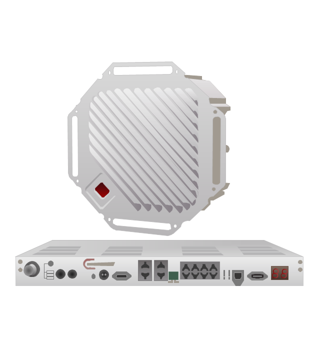
MOTOwi4 PTP 58300 wireless bridge

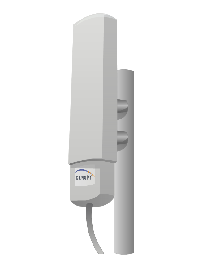
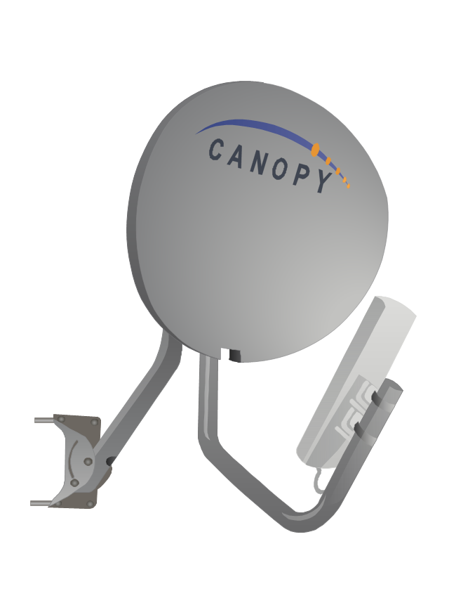
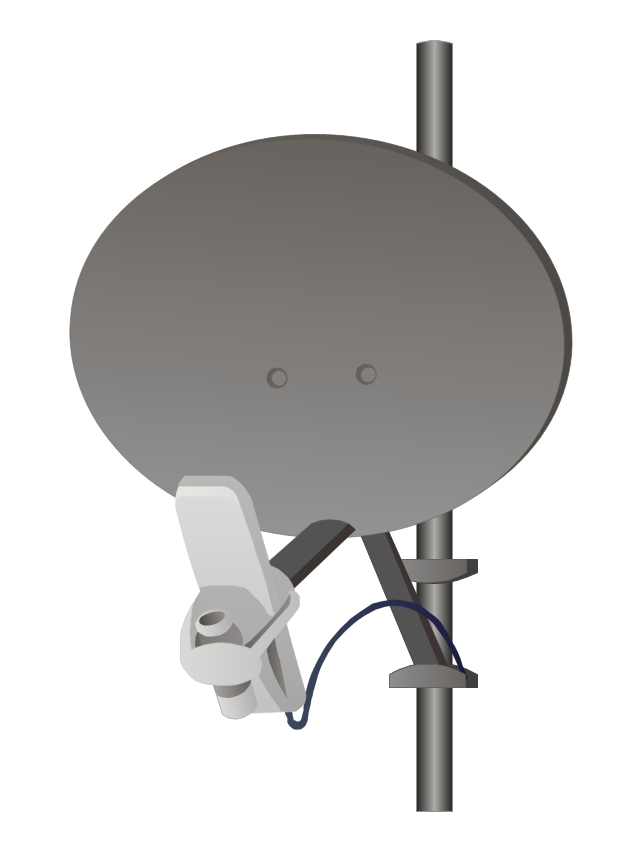
Canopy 9000SM subscriber module
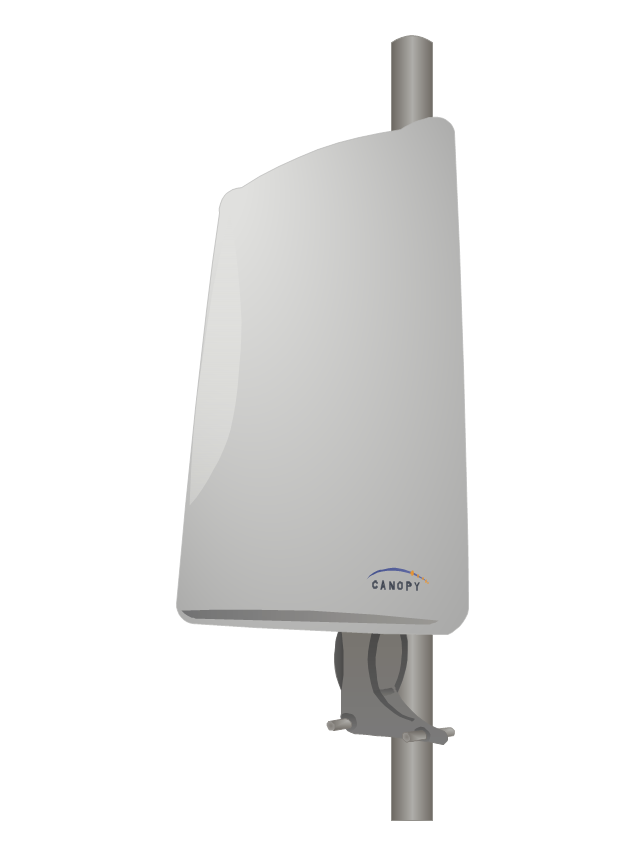
Canopy 2400SM subscriber module
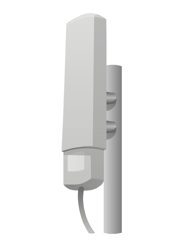
Canopy 2400BH backhaul module
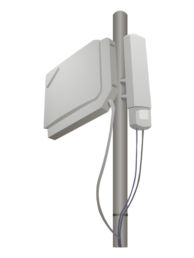
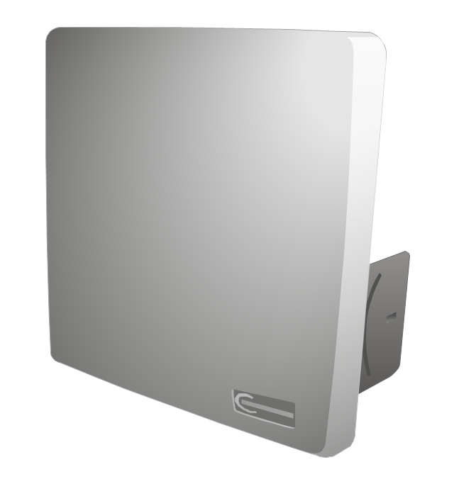
Canopy 5750AP Advantage access point module
Canopy 9000SMC connectorized subscriber module
Canopy wireless PTP 600 Ethernet bridge

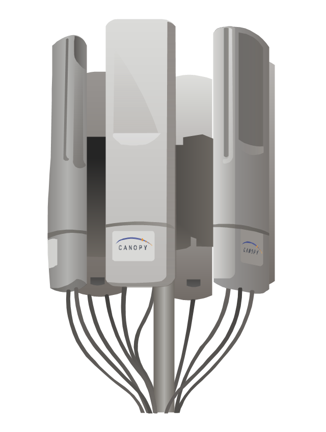
Canopy cluster management module
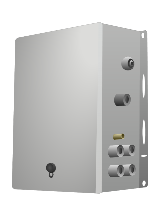
Canopy 10 Mbps wireless backhaul
Canopy 5700BHRF backhaul module
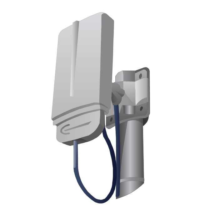
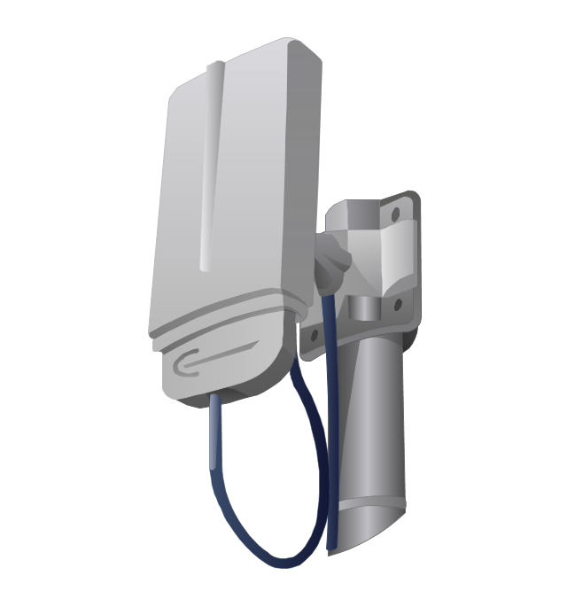
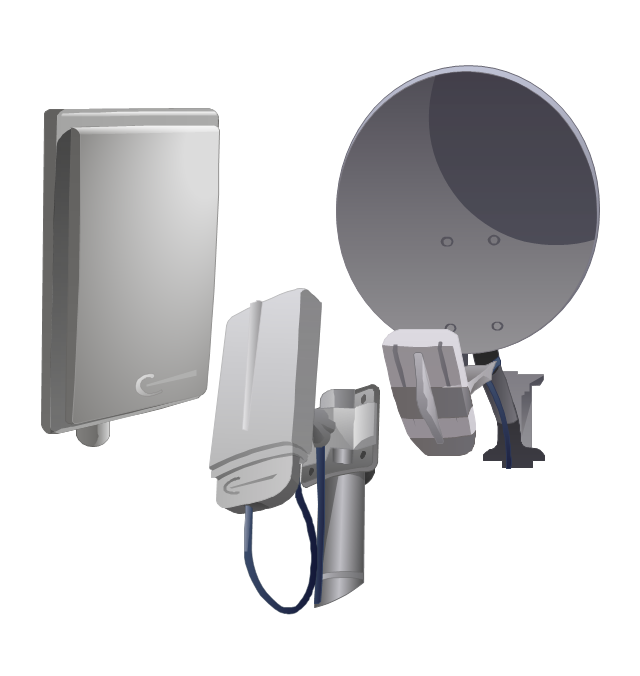
The vector stencils library "Trango" contains 10 clipart icons of Trango devices for drawing computer network diagrams and telecommunication equipment layouts.
"Trango Systems, Inc., was founded in 1996 and is headquartered in San Diego County, California. ...
Trango Systems microwave backhaul solutions and products are used in cellular/ mobile backhaul, Enterprise LAN/ WAN Bridging, All-IP Service Provider Networks, and Government/ Municipal applications." [trangosys.com]
The clip art example "Trango - Vector stencils library" was created using the ConceptDraw PRO diagramming and vector drawing software extended with the Telecommunication Network Diagrams solution from the Computer and Networks area of ConceptDraw Solution Park.
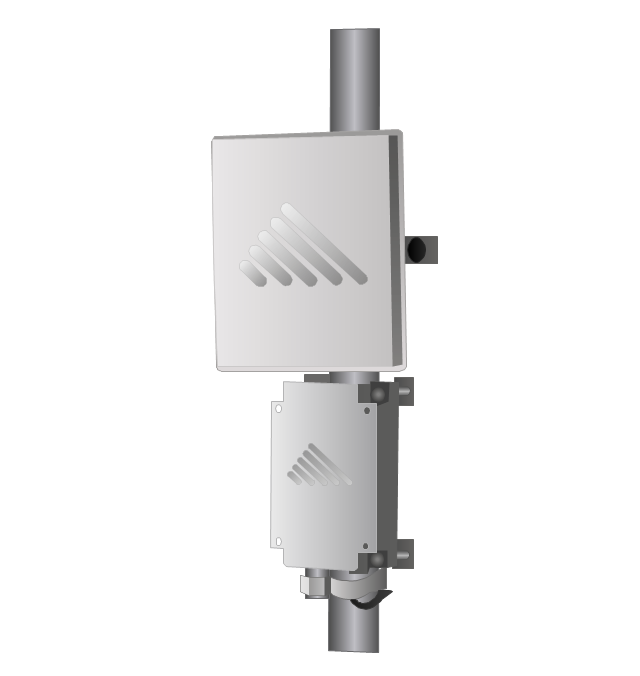
TrangoLINK Apex microwave RF link

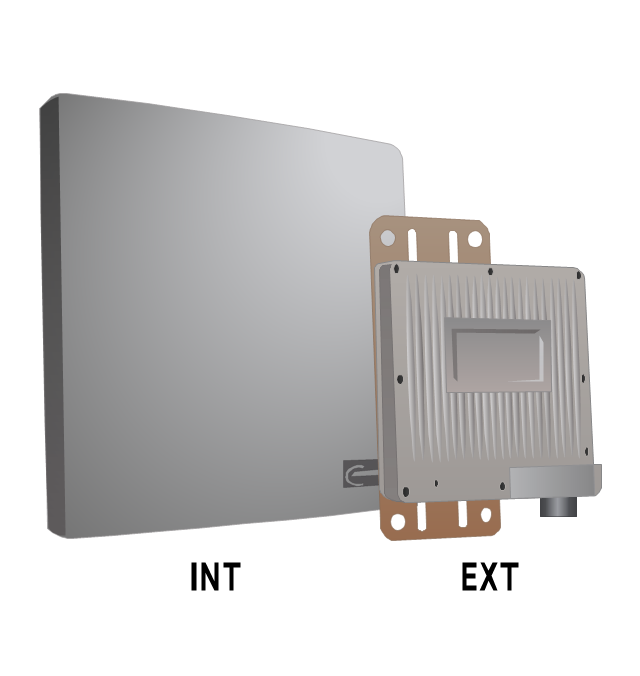
TrangoLINK Giga digital microwave radio backhaul
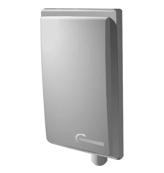
Trango AD5830-23-DP broadband antenna
Access5830 wireless access point
TrangoLINK-45 point-to-point wireless Ethernet bridge
Falcon PLUS wireless video/audio system
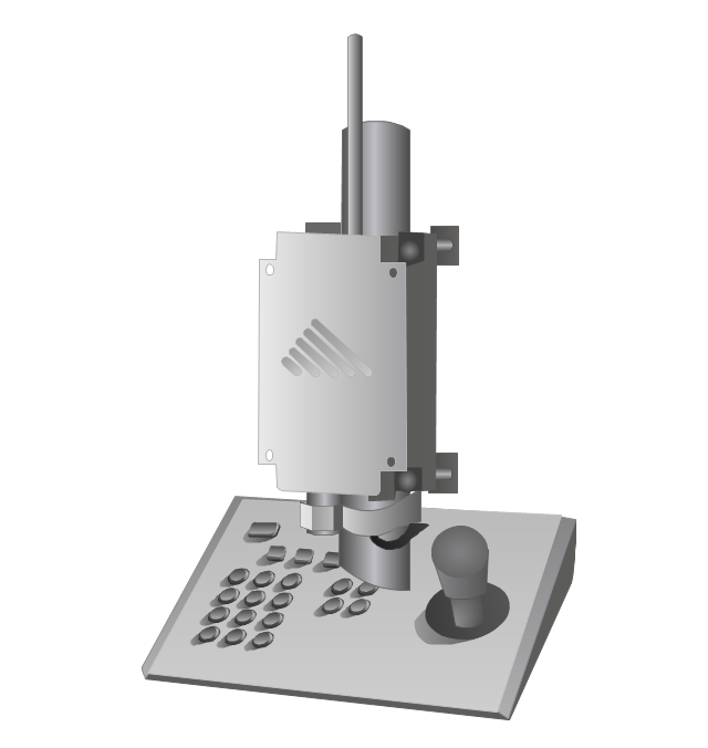
SDR900H PTZ camera control system
FOX5310 subscriber unit
Atlas FOX subscriber unit
Access5830 dual-band wireless Ethernet system
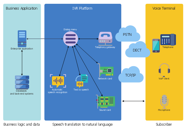
This interactive voice response (IVR) diagram sample depicts the architecture of IVR systems. It was designed on the base of the Wikimedia Commons file: IVR-Systemarchitektur.png. [commons.wikimedia.org/ wiki/ File:IVR-Systemarchitektur.png]
This file is licensed under the Creative Commons Attribution-Share Alike 3.0 Unported license. [creativecommons.org/ licenses/ by-sa/ 3.0/ deed.en]
"DTMF decoding and speech recognition are used to interpret the caller's response to voice prompts. DTMF tones are entered via the telephone keypad. ...
Other technologies include using text-to-speech (TTS) to speak complex and dynamic information, such as e-mails, news reports or weather information. TTS is computer generated synthesized speech that is no longer the robotic voice traditionally associated with computers. Real voices create the speech in fragments that are spliced together (concatenated) and smoothed before being played to the caller.
An IVR can be deployed in several ways:
1. Equipment installed on the customer premises.
2. Equipment installed in the PSTN (public switched telephone network).
3. Application service provider (ASP) / hosted IVR.
IVR can be used to provide a more sophisticated voice mail experience to the caller. ...
An automatic call distributor (ACD) is often the first point of contact when calling many larger businesses. ...
IVR call flows are created in a variety of ways. A traditional IVR depended upon proprietary programming or scripting languages, whereas modern IVR applications are generated in a similar way to Web pages, using standards such as VoiceXML, CCXML, SRGS and SSML. ...
In telecommunications, an audio response unit (ARU) is a device that provides synthesized voice responses to DTMF keypresses by processing calls based on (a) the call-originator input, (b) information received from a database, and (c) information in the incoming call, such as the time of day.
ARUs increase the number of information calls handled and provide consistent quality in information retrieval." [Interactive voice response. Wikipedia]
The IVR diagram example "IVR System Architecture" was designed using ConceptDraw PRO software extended with the Interactive Voice Response Diagrams solution from the Computer and Networks area of ConceptDraw Solution Park.
IVR diagram
 Gym and Spa Area Plans
Gym and Spa Area Plans solution extends abilities of the architects, designers, engineers, builders, marketing experts, gym instructors, fitness trainers, health and beauty services specialists. It is a real finding for all them due to the unique functionally thought-out drawing tools, samples and examples, template and libraries of pre-made vector design elements offered to help create the Gym and Spa area plans, Fitness plans, Gym workout plan, Gym layout plan, Spa design plans, Gym floor plan and Spa floor plan with any degree of detailing.
 Network Layout Floor Plans
Network Layout Floor Plans solution extends ConceptDraw DIAGRAM software functionality with powerful tools for quick and efficient documentation the network equipment and displaying its location on the professionally designed Network Layout Floor Plans. Never before creation of Network Layout Floor Plans, Network Communication Plans, Network Topologies Plans and Network Topology Maps was not so easy, convenient and fast as with predesigned templates, samples, examples and comprehensive set of vector design elements included to the Network Layout Floor Plans solution. All listed types of plans will be a good support for the future correct cabling and installation of network equipment.
 Reflected Ceiling Plans
Reflected Ceiling Plans solution extends greatly the ConceptDraw DIAGRAM functionality with samples, templates and libraries of design elements for displaying the ceiling ideas for living room, bedroom, classroom, office, shop, restaurant, and many other premises. It is an effective tool for architects, designers, builders, electricians, and other building-related people to represent their ceiling design ideas and create Reflected Ceiling plan or Reflective Ceiling plan, showing the location of light fixtures, lighting panels, drywall or t-bar ceiling patterns, HVAC grilles or diffusers that may be suspended from the ceiling. Being professional-looking and vivid, these plans perfectly reflect your ceiling ideas and can be presented to the client, in reports, in presentations, on discussions with colleagues, or successfully published in modern print or web editions.
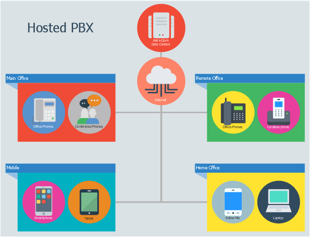
This infographic sample illustrates the hosted PBX system operation. It was designed on the base of the Wikimedia Commons file: Hosted pbx.jpg. [commons.wikimedia.org/ wiki/ File:Hosted_ pbx.jpg]
This file is licensed under the Creative Commons Attribution-Share Alike 3.0 Unported license. [creativecommons.org/ licenses/ by-sa/ 3.0/ deed.en]
"Virtual PBX systems or hosted PBX systems deliver PBX functionality as a service, available over the public switched telephone network (PSTN) or the Internet. Hosted PBXs are typically provided by a telephone company or service provider, using equipment located in the premises of a telephone exchange or the provider's data center. This means the customer does not need to buy or install PBX equipment. Generally the service is provided by a lease agreement and the provider can, in some configurations, use the same switching equipment to service multiple hosted PBX customers." [Business telephone system. Wikipedia]
The infographic example "How does the hosted PBX work" was created using the ConceptDraw PRO diagramming and vector drawing software extended with the Audio, Video, Media solution from the Illustrations area of ConceptDraw Solution Park.
Infographic
- Telecom equipment - Vector stencils library
- Network Diagram Examples | Telecom equipment - Vector stencils ...
- Telecom equipment - Vector stencils library | Telecom equipment ...
- Telecom equipment - Vector stencils library | Telecom equipment ...
- Telecom equipment - Vector stencils library | Telecommunication ...
- Telecom equipment - Vector stencils library | Telecommunication ...
- Telecom equipment - Vector stencils library
- Telecom equipment - Vector stencils library | Computers and ...
- Telecommunication Network Diagrams | Telecom equipment ...
- Telecom equipment - Vector stencils library | Wireless Networks ...