The vector stencils library Alarm and access control contains 80 symbols of digital proximity equipment, locking hardware, and access control equipment.
"An alarm device or system of alarm devices gives an audible, visual or other form of alarm signal about a problem or condition. Alarm devices are often outfitted with a siren." [Alarm device. Wikipedia]
"An access control point, which can be a door, turnstile, parking gate, elevator, or other physical barrier, where granting access can be electronically controlled. Typically, the access point is a door. An electronic access control door can contain several elements. At its most basic, there is a stand-alone electric lock. The lock is unlocked by an operator with a switch. To automate this, operator intervention is replaced by a reader. The reader could be a keypad where a code is entered, it could be a card reader, or it could be a biometric reader. Readers do not usually make an access decision, but send a card number to an access control panel that verifies the number against an access list. To monitor the door position a magnetic door switch can be used. In concept, the door switch is not unlike those on refrigerators or car doors. Generally only entry is controlled, and exit is uncontrolled. In cases where exit is also controlled, a second reader is used on the opposite side of the door. In cases where exit is not controlled, free exit, a device called a request-to-exit (REX) is used. Request-to-exit devices can be a push-button or a motion detector. When the button is pushed, or the motion detector detects motion at the door, the door alarm is temporarily ignored while the door is opened. Exiting a door without having to electrically unlock the door is called mechanical free egress. This is an important safety feature. In cases where the lock must be electrically unlocked on exit, the request-to-exit device also unlocks the door." [Access control. Wikipedia]
Use the design elements library Alarm and access control for drawing layout floor plans, blueprints, and wiring diagrams of intrusion systems, time and attendance systems, card and code access control security systems, internal and external security control systems using the ConceptDraw PRO diagramming and vector drawing software.
The shapes library Alarm and access control is included in the Security and Access Plans solution from the Building Plans area of ConceptDraw Solution Park.
Alarm and access control symbols

Physical Security Plan

How To use House Electrical Plan Software


Electrical Symbols, Electrical Diagram Symbols

Cafe Floor Plan Design Software

HelpDesk
How to Draw a Pareto Chart

HelpDesk
How to Draw Physics Diagrams in ConceptDraw PRO
")
Electrical Drawing Software and Electrical Symbols

HelpDesk
How to Draw a Chemical Process Flow Diagram

This cafe electrical floor plan sample shows the outlet and switch layout.
"An electrical drawing, is a type of technical drawing that shows information about power, lighting, and communication for an engineering or architectural project. Any electrical working drawing consists of "lines, symbols, dimensions, and notations to accurately convey an engineering's design to the workers, who install the electrical system on the job".
A complete set of working drawings for the average electrical system in large projects usually consists of:
(1) A plot plan showing the building's location and outside electrical wiring.
(2) Floor plans showing the location of electrical systems on every floor.
(3) Power-riser diagrams showing panel boards.
(4) Control wiring diagrams.
(5) Schedules and other information in combination with construction drawings.
Electrical drafters prepare wiring and layout diagrams used by workers who erect, install, and repair electrical equipment and wiring in communication centers, power plants, electrical distribution systems, and buildings." [Electrical drawing. Wikipedia]
The outlet and switch layout example "Cafe electrical floor plan" was created using the ConceptDraw PRO diagramming and vector drawing software extended with the Electric and Telecom Plans solution from the Building Plans area of ConceptDraw Solution Park.
Outlet and switch layout

The vector stencils library "Qualifying" contains 56 qualifying symbols of radiation, polarity, phase, windings, wire, ground, connection, connector, coaxial, electret.
Use these signs to annotate or specify characteristics of objects in electrical drawings, electronic schematics, circuit diagrams, electromechanical drawings, and wiring diagrams, cabling layout diagrams.
"An electrical drawing, is a type of technical drawing that shows information about power, lighting, and communication for an engineering or architectural project. Any electrical working drawing consists of "lines, symbols, dimensions, and notations to accurately convey an engineering's design to the workers, who install the electrical system on the job".
A complete set of working drawings for the average electrical system in large projects usually consists of:
(1) A plot plan showing the building's location and outside electrical wiring.
(2) Floor plans showing the location of electrical systems on every floor.
(3) Power-riser diagrams showing panel boards.
(4) Control wiring diagrams.
(5) Schedules and other information in combination with construction drawings.
Electrical drafters prepare wiring and layout diagrams used by workers who erect, install, and repair electrical equipment and wiring in communication centers, power plants, electrical distribution systems, and buildings." [Electrical drawing. Wikipedia]
The signs example "Design elements - Qualifying" was drawn using the ConceptDraw PRO diagramming and vector drawing software extended with the Electrical Engineering solution from the Engineering area of ConceptDraw Solution Park.
Qualifying symbols

The vector stencils library "Electrical and telecom" contains 83 symbols of electrical and telecommunication equipment for electrical drawings and wiring diagrams of buildings, communication centers, power plants and electrical distribution systems.
"An electrical drawing, is a type of technical drawing that shows information about power, lighting, and communication for an engineering or architectural project." [Electrical drawing. Wikipedia]
Use the design elements library "Electrical and telecom" to design your own electrical drawings, plot plans of the building outside electrical wiring, floor plans with electrical and telecommunication systems layout, power-riser diagrams with panel boards, control wiring diagrams and cabling layout schemes, reflected ceiling plans and lighting panels layouts using the ConceptDraw PRO diagramming and vector drawing software.
The shapes library "Electrical and telecom" is included in the Electric and Telecom Plans solution from the Building Plans area of ConceptDraw Solution Park.
Electrical and telecom symbols

The vector stencils library Initiation and annunciation contains 9 symbols of Fire Alarm Control Panel (FACP) or Fire Alarm Control Unit (FACU) elements, triggering devices, audible alarm systems, timers, security control equipment, and recording devices.
"A Fire Alarm Control Panel (FACP), or Fire Alarm Control Unit (FACU), is the controlling component of a Fire Alarm System. The panel receives information from environmental sensors designed to detect changes associated with fire, monitors their operational integrity and provides for automatic control of equipment, and transmission of information necessary to prepare the facility for fire based on a predetermined sequence. The panel may also supply electrical energy to operate any associated sensor, control, transmitter, or relay. There are four basic types of panels: coded panels, conventional panels, addressable panels, and multiplex systems." [Fire alarm control panel. Wikipedia]
Use the shapes library Initiation and annunciation to draw layout floor plans, communications schematics and wiring diagrams of security systems using the ConceptDraw PRO diagramming and vector drawing software.
The design elements library Initiation and annunciation is included in the Security and Access Plans solution from the Building Plans area of ConceptDraw Solution Park.
Initiation and annunciation symbols

The vector stencils library "Alarm and access control" contains 80 shapes of digital proximity equipment, locking hardware, and access control equipment. Use it for drawing security and access plans of intrusion systems, time and attendance systems, and card and code access control security systems with ConceptDraw PRO software extended with the Security and Access Plans solution from the Building Plans area of ConceptDraw Solution Park.
Card reader with keypad
Biometric access
Card access
Keypad device
Keypad
Security keypad

Horn / siren
Weatherproof horn / siren
Horn / strobe
Strobe

Card reader with time
Turnstile

Revolving door

Traffic arm
Vehicle loop detector
Smoke detector

Heat detector

Gas detector
Carbon monoxide detector
Flood sensor

Electronic lock
Exit device
Pushbutton

Panic button

Camera with keypad
Camera

Camera with intercom
Camera with card reader
Security window screen
Window contact sensor
Vibration / shock sensor

Screen alarm

Glass break detector
Door contact sensor
Floor mat

Driveway sensor
Overhead door contact sensor

Wall motion sensor

Floor motion sensor

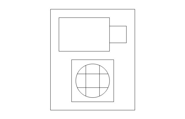
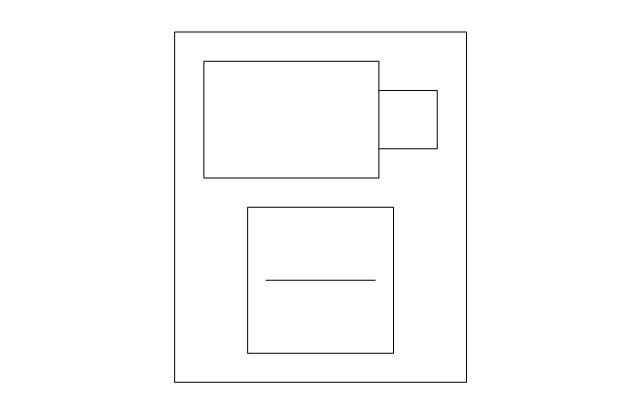
Security control unit
Security door contact
Security control panel
Security card reader
Motion detector

Master intercom

Magnetic lock, security door alarm

Intercom unit
Electric door strike
Electric door opener
Door buzzer
Door chime
Doorbell
Volumetric capacity detector
Siren
Receiver

PIR field of view

Mains supply power source

Infrared detector
Heat detector

Foil on glass detector
Dial-up remote equipment
Beam fence disturbance
User control keyswitch
User control digital keypad
Ultrasonic transceiver

Transformer

Space detection device

Slave tape dialer
Slave digital communicator
Remote zone annunciator
Passive infrared

Microwave transceiver

Line cut monitor

Infrasonic

Foil

Emergency power / battery

Dual technology device

Control unit

Contact switch surface

Contact switch flush

HelpDesk
How to Remove ConceptDraw Products from Mac and PC

- Control Panel Wiring Diagram Software
- Electrical Control Panel Layout Software Free Download
- Security and Access Plans | How to Draw a Security and Access ...
- Electrical Panel Plan Drawing Symbol
- Fire Alarm Symbols For Drawings
- Electrical Control Panel Board Design Software Free Download
- Design elements - Qualifying | Cafe electrical floor plan | Panel ...
- Design elements - Alarm and access control | Mechanical Drawing ...
- Electrical Panel Board Erection
- Design elements - Qualifying | Cafe electrical floor plan | Design ...
- Electrical Symbol Of Indicator Panel
- Electrical Control Drawing Software
- Electrical Panel Drawing Symbols
- Motion Sensor Connections To Lighting Control Panel
- Power Plant Electrical System Drawing Symbols
- Design elements - Alarm and access control | CAD Drawing ...
- Electrical Control Panel Board Wiring Diagram Symbol
- Symbol Use For Panel Board For Lighting
- How To use House Electrical Plan Software | Electrical Drawing ...