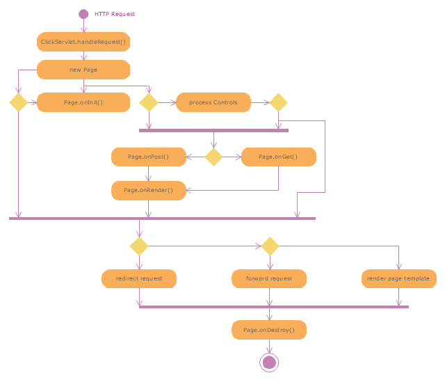
"Web container (also known as a Servlet container) is the component of a web server that interacts with Java servlets. A web container is responsible for managing the lifecycle of servlets, mapping a URL to a particular servlet and ensuring that the URL requester has the correct access rights. A web container implements the web component contract of the Java EE architecture, specifying a runtime environment for web components that includes security, concurrency, lifecycle management, transaction, deployment, and other services. A web container provides the same services as a JSP container as well as a federated view of the Java EE platform APIs." [Web container. Wikipedia]
The UML activity diagram example "Servlet container" was created using the ConceptDraw PRO diagramming and vector drawing software extended with the Rapid UML solution from the Software Development area of ConceptDraw Solution Park.
The UML activity diagram example "Servlet container" was created using the ConceptDraw PRO diagramming and vector drawing software extended with the Rapid UML solution from the Software Development area of ConceptDraw Solution Park.
UML activity diagram
The vector stencils library "Logical network diagram" contains 16 symbols for drawing logical computer network diagrams.
"The logical topology ... is the way that the signals act on the network media, or the way that the data passes through the network from one device to the next without regard to the physical interconnection of the devices. A network's logical topology is not necessarily the same as its physical topology. ...
The logical classification of network topologies generally follows the same classifications as those in the physical classifications of network topologies but describes the path that the data takes between nodes being used as opposed to the actual physical connections between nodes. The logical topologies are generally determined by network protocols as opposed to being determined by the physical layout of cables, wires, and network devices or by the flow of the electrical signals, although in many cases the paths that the electrical signals take between nodes may closely match the logical flow of data, hence the convention of using the terms logical topology and signal topology interchangeably.
Logical topologies are often closely associated with Media Access Control methods and protocols. Logical topologies are able to be dynamically reconfigured by special types of equipment such as routers and switches." [Network topology. Wikipedia]
The symbols example "Logical network diagram - Vector stencils library" was created using the ConceptDraw PRO diagramming and vector drawing software extended with the Computer and Networks solution from the Computer and Networks area of ConceptDraw Solution Park.
www.conceptdraw.com/ solution-park/ computer-and-networks
Server

Disk

Printer

Domain

Network

File

Group

Root

Shared Admin

Directory

Tree

NDS Container

Unknown

Neightborhood

Service

Information

The vector stencils library "Logical network diagram" contains 16 symbols for drawing logical computer network diagrams.
"The logical topology ... is the way that the signals act on the network media, or the way that the data passes through the network from one device to the next without regard to the physical interconnection of the devices. A network's logical topology is not necessarily the same as its physical topology. ...
The logical classification of network topologies generally follows the same classifications as those in the physical classifications of network topologies but describes the path that the data takes between nodes being used as opposed to the actual physical connections between nodes. The logical topologies are generally determined by network protocols as opposed to being determined by the physical layout of cables, wires, and network devices or by the flow of the electrical signals, although in many cases the paths that the electrical signals take between nodes may closely match the logical flow of data, hence the convention of using the terms logical topology and signal topology interchangeably.
Logical topologies are often closely associated with Media Access Control methods and protocols. Logical topologies are able to be dynamically reconfigured by special types of equipment such as routers and switches." [Network topology. Wikipedia]
The symbols example "Logical network diagram - Vector stencils library" was created using the ConceptDraw PRO diagramming and vector drawing software extended with the Computer and Networks solution from the Computer and Networks area of ConceptDraw Solution Park.
www.conceptdraw.com/ solution-park/ computer-and-networks
"The logical topology ... is the way that the signals act on the network media, or the way that the data passes through the network from one device to the next without regard to the physical interconnection of the devices. A network's logical topology is not necessarily the same as its physical topology. ...
The logical classification of network topologies generally follows the same classifications as those in the physical classifications of network topologies but describes the path that the data takes between nodes being used as opposed to the actual physical connections between nodes. The logical topologies are generally determined by network protocols as opposed to being determined by the physical layout of cables, wires, and network devices or by the flow of the electrical signals, although in many cases the paths that the electrical signals take between nodes may closely match the logical flow of data, hence the convention of using the terms logical topology and signal topology interchangeably.
Logical topologies are often closely associated with Media Access Control methods and protocols. Logical topologies are able to be dynamically reconfigured by special types of equipment such as routers and switches." [Network topology. Wikipedia]
The symbols example "Logical network diagram - Vector stencils library" was created using the ConceptDraw PRO diagramming and vector drawing software extended with the Computer and Networks solution from the Computer and Networks area of ConceptDraw Solution Park.
www.conceptdraw.com/ solution-park/ computer-and-networks
Server
Disk
Printer
Domain
Network
File
Group
Root
Shared Admin
Directory
Tree
NDS Container
Unknown
Neightborhood
Service
Information
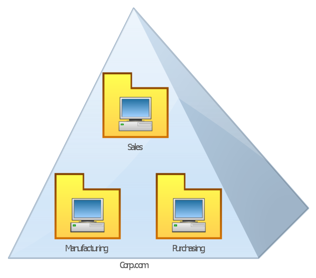
This AD diagram example was redesigned from the picture "Single root domain with a structured OU model" from the book "Active Directory for Dummies".
"A domain is the cornerstone that you lay whenever you create trees and forests. Regardless of whether you design a tree or a forest, the starting point is always the root domain. The root domain is the first domain that you create in your AD structure, and it sits at the top of your diagram.
The root domain of your tree, similar to any other domain, is a grouping of
resources built on the following components:
(1) Domain controllers.
(2) Security policies. ...
For many small and medium-sized companies, a single root domain with a
structured OU (organizational unit) model... provides sufficient flexibility for an AD tree. ...
However, larger companies, companies with complex organization charts, and
companies with multiple sites often find that a single domain isn’t suitable." [Steve Clines and Marcia Loughry, Active Directory® For Dummies®, 2nd Edition. 2008]
The Active Directory diagram example "Single root domain with a structured OU model" was created using the ConceptDraw PRO diagramming and vector drawing software extended with the Active Directory Diagrams solution from the Computer and Networks area of ConceptDraw Solution Park.
Active Directory network diagram
"In electronics, a vacuum tube, electron tube (in North America), tube, or thermionic valve or valve (in British English) is a device controlling electric current through a vacuum in a sealed container. The simplest vacuum tube, the diode, contains only two elements; current can only flow in one direction through the device between the two electrodes, as electrons emitted by the hot cathode travel through the tube and are collected by the anode. Addition of a third and additional electrodes allows the current flowing between cathode and anode to be controlled in various ways. The device can be used as an electronic amplifier, a rectifier, an electronically controlled switch, an oscillator, and for other purposes.
Vacuum tubes mostly rely on thermionic emission of electrons from a hot filament or a cathode heated by the filament. Some electron tube devices rely on the properties of a discharge through an ionized gas." [Vacuum tube. Wikipedia]
"The EL34 is a thermionic valve or vacuum tube of the power pentode type. It has an international octal base (indicated by the '3' in the part number) and is found mainly in the final output stages of audio amplification circuits and was designed to be suitable as a series regulator by virtue of its high permissible voltage between heater and cathode and other parameters. The American RETMA tube designation number for this tube is 6CA7. Russian analog is 6P27S (Cyrillic: 6П27C )" [EL34. Wikipedia]
This circuit diagram sample was redrawn from the Wikipedia Commons file: EL34 schematics (circuit diagram).gif. [commons.wikimedia.org/ wiki/ File:EL34_ schematics_ %28circuit_ diagram%29.gif]
The example "Circuit diagram - EL 34 schematics" was drawn using the ConceptDraw PRO diagramming and vector drawing software extended with the Electrical Engineering solution from the Engineering area of ConceptDraw Solution Park.
EL34 shemathics

 Rapid UML
Rapid UML solution extends ConceptDraw DIAGRAM software with templates, samples and libraries of vector stencils for quick drawing the UML diagrams using Rapid Draw technology.
ConceptDraw DIAGRAM Compatibility with MS Visio

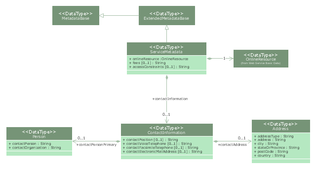
"Metadata is "data about data". The term is ambiguous, as it is used for two fundamentally different concepts (types). Structural metadata is about the design and specification of data structures and is more properly called "data about the containers of data"; descriptive metadata, on the other hand, is about individual instances of application data, the data content.
Metadata are traditionally found in the card catalogs of libraries. As information has become increasingly digital, metadata are also used to describe digital data using metadata standards specific to a particular discipline. By describing the contents and context of data files, the quality of the original data/ files is greatly increased. For example, a webpage may include metadata specifying what language it is written in, what tools were used to create it, and where to go for more on the subject, allowing browsers to automatically improve the experience of users." [Metadata. Wikipedia]
The UML class diagram example "Metadata information model" was created using the ConceptDraw PRO diagramming and vector drawing software extended with the Rapid UML solution from the Software Development area of ConceptDraw Solution Park.
UML class diagram
- UML activity diagram - Servlet container | Circular Arrows Diagrams ...
- UML activity diagram - Servlet container | UML Activity Diagram ...
- UML activity diagram - Servlet container | AWS simple icons v2.0 ...
- UML activity diagram - Servlet container | Rapid UML | Servlet ...
- UML activity diagram - Servlet container | Security and Access Plans ...
- UML activity diagram - Servlet container | UML Diagram Types ...
- UML activity diagram - Servlet container
- UML activity diagram - Servlet container | Diagramming Software for ...
- Drawing Of Container Ship With Safety Plan
- UML interaction overview diagram - Online shopping | UML activity ...
- Website launch - Flowchart | UML activity diagram - Servlet ...
- Diagramming Software for Design UML Activity Diagrams | UML ...
- How to Save a Diagram as a Web Page in ConceptDraw PRO | UML ...
- Server Diagram Items
- Logical network diagram - Vector stencils library | Nds Container
- Container Tracking System Data Flow Diagram
- State Diagram Example - Online Store | UML interaction overview ...
- UML activity diagram - Servlet container | Design elements - Android ...
- UML interaction overview diagram - Online shopping | Online ...