"RT-middleware (Robotics Technology Middleware) is a common platform standards for Robots based on the distributed object technology. RT-middleware supports the construction of various networked robotic systems by the integration of various network enabled robotic elements called RT-Components. The specification standard of the RT-component is discussed / defined by the Object Management Group (OMG). ...
In the RT-middleware, robotics elements, such as actuators, are regarded as RT-components, and the whole robotic system is constructed by connecting those RT-components. This distributed architecture helps developers to re-use the robotic elements, and boosts the reliability of the robotic system.
Each RT-component has port as an endpoint for communicating other RT-components. Every port has its type and the ports which have the same type can be connected each other.
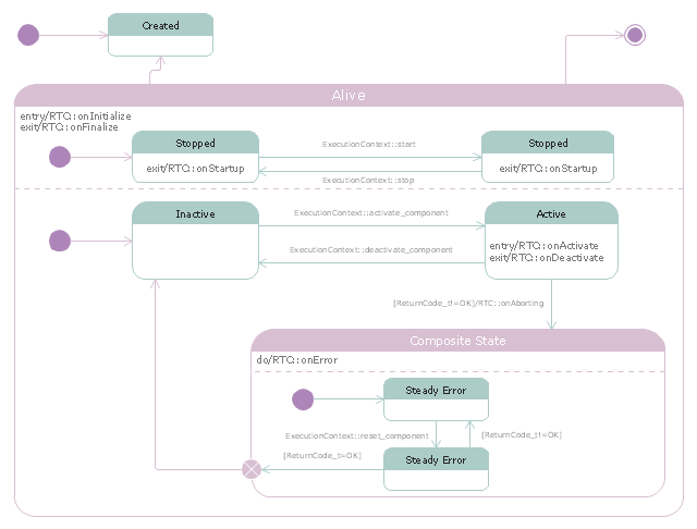
RT-components also has its state, so the RT-components behaves as state machines. The states that RT-components can have are CREATED, INACTIVE, ACTIVE, and ERROR, and the states and behaviors are controlled by the execution-context. If developers want to change the behavior of their RT-components, the execution-context can be replaced at run-time." [RT middleware. Wikipedia]
The UML state machine diagram example "State transitions of RT-component" was created using the ConceptDraw PRO diagramming and vector drawing software extended with the Rapid UML solution from the Software Development area of ConceptDraw Solution Park.
In the RT-middleware, robotics elements, such as actuators, are regarded as RT-components, and the whole robotic system is constructed by connecting those RT-components. This distributed architecture helps developers to re-use the robotic elements, and boosts the reliability of the robotic system.
Each RT-component has port as an endpoint for communicating other RT-components. Every port has its type and the ports which have the same type can be connected each other.
RT-components also has its state, so the RT-components behaves as state machines. The states that RT-components can have are CREATED, INACTIVE, ACTIVE, and ERROR, and the states and behaviors are controlled by the execution-context. If developers want to change the behavior of their RT-components, the execution-context can be replaced at run-time." [RT middleware. Wikipedia]
The UML state machine diagram example "State transitions of RT-component" was created using the ConceptDraw PRO diagramming and vector drawing software extended with the Rapid UML solution from the Software Development area of ConceptDraw Solution Park.
UML state machine diagram
 Flowcharts
The Flowcharts solution for ConceptDraw DIAGRAM is a comprehensive set of examples and samples in several varied color themes for professionals that need to represent graphically a process. Solution value is added by the basic flow chart template and shapes' libraries of flowchart notation. ConceptDraw DIAGRAM flow chart creator lets one depict the processes of any complexity and length, as well as design the Flowchart either vertically or horizontally.
ERD Symbols and Meanings


 Electric and Telecom Plans
The Electric and Telecom Plans solution providing the electric and telecom-related stencils, floor plan electrical symbols and pre-made examples is useful for electricians, interior designers, telecommunications managers, builders and other technicians when creating the electric visual plans and telecom drawings, home electrical plan, residential electric plan, telecom wireless plan, electrical floor plans whether as a part of the building plans or the independent ones.
 HR Flowcharts
Human resource management diagrams show recruitment models, the hiring process and human resource development of human resources.
Circuits and Logic Diagram Software

IDEF1X Standard

- Design elements - Walls, shell and structure | UML Flowchart ...
- UML Block Diagram | UML Class Diagram Example - Buildings and ...
- Sport Field Plans | UML Diagram of Parking | Aerospace and ...
- UML Diagram of Parking | Site Plans | Event-driven Process Chain ...
- Emergency Plan | Diagramming Software for Design UML Object ...
- Basic Flowchart Symbols and Meaning | Design elements - Walls ...
- UML Diagram of Parking | Sport Field Plans | Bank ATM use case ...
- UML Diagram of Parking | Basic Flowchart Symbols and Meaning ...
- Sign Making Software | Credit Card Processing System UML ...
- UML Class Diagram Example - Buildings and Rooms | How To Draw ...
- Project —Task Trees and Dependencies | PM Easy | Financial Trade ...
- UML Diagram of Parking | Site Plans | UML Activity Diagram | What ...
- UML Diagram of Parking | Diagramming Software for Design UML ...
- Process Flowchart | Diagramming Software for Design UML State ...
- Cisco Buildings. Cisco icons, shapes, stencils and symbols ...
- UML Diagram of Parking | Event-driven Process Chain Diagrams ...
- UML activity diagram - Alarm trigger processing | Fire safety ...
- Design elements - Outlets | Design elements - Bank UML ...
- UML Diagram of Parking | Design elements - Parking and roads ...
- UML Use Case Diagram Example - Taxi Service | Business Process ...