 Basic Diagramming
This solution extends ConceptDraw PRO software with the specific tools you need to easily draw flowcharts, block diagrams, histograms, pie charts, divided bar diagrams, line graphs, circular arrows diagrams, Venn diagrams, bubble diagrams and concept maps
 Computer and Networks Area
The solutions from Computer and Networks Area of ConceptDraw Solution Park collect samples, templates and vector stencils libraries for drawing computer and network diagrams, schemes and technical drawings.
 Software Development
This solution extends ConceptDraw PRO v9.4 and helps to accelerate and simplify software development and design by allowing you to draw UML diagrams and prototype Windows and Mac OS user interfaces.
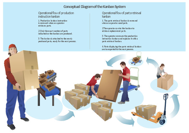
"Kanban ... (literally signboard or billboard) is a scheduling system for lean and just-in-time (JIT) production. Kanban is a system to control the logistical chain from a production point of view, and is not an inventory control system. Kanban was developed by Taiichi Ohno, at Toyota, to find a system to improve and maintain a high level of production. Kanban is one method through which JIT is achieved.
Kanban became an effective tool in support of running a production system as a whole, and it proved to be an excellent way for promoting improvement. Problem areas were highlighted by reducing the number of kanban in circulation." [Kanban. Wikipedia]
The example "Conceptual diagram of the Kanban System" was created in the ConceptDraw PRO diagramming and vector drawing software using the vector stencils library Packaging, loading, customs.
The example "Conceptual diagram of the Kanban System" is included in the Manufacturing and Maintenance solution from the Illustration area of ConceptDraw Solution Park.
Infographics
 Computer Network Diagrams
Computer Network Diagrams solution extends ConceptDraw PRO software with samples, templates and libraries of vector icons and objects of computer network devices and network components to help you create professional-looking Computer Network Diagrams, to plan simple home networks and complex computer network configurations for large buildings, to represent their schemes in a comprehensible graphical view, to document computer networks configurations, to depict the interactions between network's components, the used protocols and topologies, to represent physical and logical network structures, to compare visually different topologies and to depict their combinations, to represent in details the network structure with help of schemes, to study and analyze the network configurations, to communicate effectively to engineers, stakeholders and end-users, to track network working and troubleshoot, if necessary.
Data structure diagram with ConceptDraw PRO

 Manufacturing and Maintenance
Manufacturing and maintenance solution extends ConceptDraw PRO software with illustration samples, templates and vector stencils libraries with clip art of packaging systems, industrial vehicles, tools, resources and energy.
The vector stencils library "Hydraulic pumps and motors" contains 74 symbols of hydraulic pump vector stencils, hydraulic motor symbols for engineering drawings of fluid power and hydraulic control systems.
"Hydraulic pumps are used in hydraulic drive systems and can be hydrostatic or hydrodynamic.
Hydrostatic pumps are positive displacement pumps while hydrodynamic pumps can be fixed displacement pumps, in which the displacement (flow through the pump per rotation of the pump) cannot be adjusted, or variable displacement pumps, which have a more complicated construction that allows the displacement to be adjusted." [Hydraulic pump. Wikipedia]
"A hydraulic motor is a mechanical actuator that converts hydraulic pressure and flow into torque and angular displacement (rotation). The hydraulic motor is the rotary counterpart of the hydraulic cylinder.
Conceptually, a hydraulic motor should be interchangeable with a hydraulic pump because it performs the opposite function - much as the conceptual DC electric motor is interchangeable with a DC electrical generator. However, most hydraulic pumps cannot be used as hydraulic motors because they cannot be backdriven. Also, a hydraulic motor is usually designed for the working pressure at both sides of the motor.
Hydraulic pumps, motors, and cylinders can be combined into hydraulic drive systems. One or more hydraulic pumps, coupled to one or more hydraulic motors, constitutes a hydraulic transmission." [Hydraulic motor. Wikipedia]
The shapes example "Design elements - Hydraulic pumps and motors" was created using the ConceptDraw PRO diagramming and vector drawing software extended with the Mechanical Engineering solution from the Engineering area of ConceptDraw Solution Park.
Hydraulic pump and motor symbols

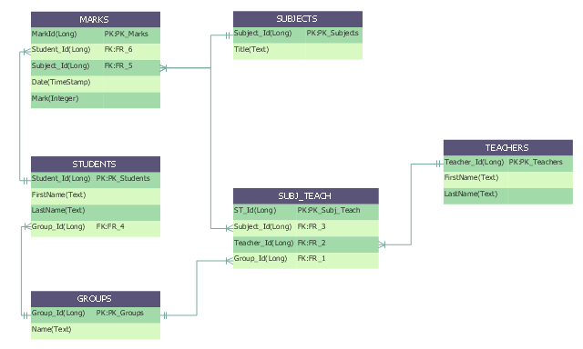
"An ER model is an abstract way of describing a database. In the case of a relational database, which stores data in tables, some of the data in these tables point to data in other tables - for instance, your entry in the database could point to several entries for each of the phone numbers that are yours. The ER model would say that you are an entity, and each phone number is an entity, and the relationship between you and the phone numbers is 'has a phone number'. Diagrams created to design these entities and relationships are called entity–relationship diagrams or ER diagrams.
Using the three schema approach to software engineering, there are three levels of ER models that may be developed. ...
Conceptual data model ... is the highest level ER model in that it contains the least granular detail but establishes the overall scope of what is to be included within the model set.
Logical ER model ... contains more detail than the conceptual ER model. In addition to master data entities, operational and transactional data entities are now defined.
The physical ER model is normally developed to be instantiated as a database. Therefore, each physical ER model must contain enough detail to produce a database and each physical ER model is technology dependent since each database management system is somewhat different.
Physical model ... is normally forward engineered to instantiate the structural metadata into a database management system as relational database objects such as database tables, database indexes such as unique key indexes, and database constraints such as a foreign key constraint or a commonality constraint." [Entity–relationship model. Wikipedia]
This crow's foot entity-relationship diagram (ERD) example "Educational data base" was created using the ConceptDraw PRO diagramming and vector drawing software extended with the Entity-Relationship Diagram (ERD) solution from the Software Development area of ConceptDraw Solution Park.
ERD
- Conceptdraw.com: Mind Map Software, Drawing Tools | Project ...
- ConceptDraw PRO The best Business Drawing Software | Business ...
- How To Create Restaurant Floor Plans in Minutes | Data structure ...
- ConceptDraw PRO The best Business Drawing Software
- Software Development | ConceptDraw PRO The best Business ...
- Concept Maps | Concept maps with ConceptDraw PRO | Simple ...
- Concept map - Internet marketing | Concept maps with ...
- Concept maps with ConceptDraw PRO | Basic Diagramming | The ...
- Basic Diagramming | Simple Drawing Applications for Mac | Bubble ...
- Data Flow Diagrams with ConceptDraw PRO - Conceptdraw.com
- Entity-Relationship Diagram (ERD) | ConceptDraw PRO Database ...
- Conceptual diagram of the Kanban System | Value stream with ...
- Computer and Networks Software | ConceptDraw.com
- Vehicular Networking | Computer and Networks Area | Aerospace ...
- Entity Relationship Diagram Software Engineering | Engineering ...
- ConceptDraw PRO Database Modeling Software | Entity ...
- Basic Diagramming | Computer and Networks Area | Computer and ...
- How to Draw an Organization Chart | How to Draw a Computer ...
- Illustration | Basic Diagramming | Presentation Clipart |
- Data structure diagram with ConceptDraw PRO | Organizational ...