Metropolitan area networks (MAN). Computer and Network Examples
. Computer and Network Examples")

Components of ER Diagram

ERD Symbols and Meanings


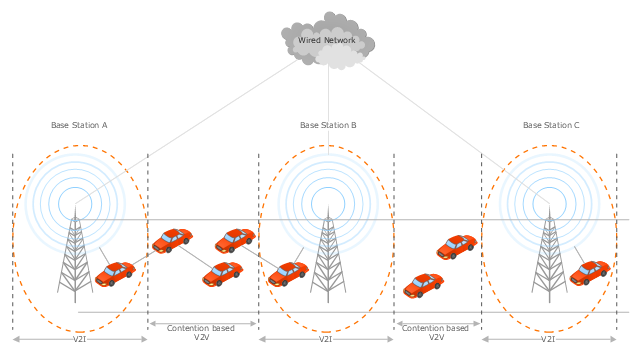
This vehicular network diagram sample was drawn on the base of the picture "Inter-Vehicle Communication (IVC) systems" from the website of the Department of Electrical and Computer Engineering, the Ohio State University.
[www2.ece.ohio-state.edu/ ~ekici/ res_ ivc.html]
"Driver assistance systems are meant to support drivers with driving process in order to avoid traffic accidents, speed up the traffic and have a higher control over the traffic in general. There are a lot of systems which give support to the drivers, such as adaptive cruise control, traffic sign recognition, automatic parking, etc. ... the vehicular communication systems ... use the capacity of the vehicles to communicate, not only between them but also with infrastructures. All the information is collected and processed to offer use
ful services. Wireless Sensor Networks (WSN) are widely used in this area. With the incoming upgrades of these networks, they are becoming an attractive solution to give support with the communication mechanisms between vehicles." [mi.fu-berlin.de/ inf/ groups/ ag-tech/ teaching/ 2011_ SS/ S_ 19510b_ Proseminar_ Technische_ Informatik/ daniel-lopez-report.pdf?1346662267]
The vehicular network diagram example "Inter-vehicle communication systems" was created using the ConceptDraw PRO diagramming and vector drawing software extended with the Vehicular Networking solution from the Computer and Networks area of ConceptDraw Solution Park.
Vehicular network diagram
- Computer Network . Computer and Network Examples | Point to ...
- Computer Network . Computer and Network Examples | UML ...
- Computer Networks Explain Diagram In Hindi
- Computer Network . Computer and Network Examples | Fully ...
- Metropolitan area networks (MAN). Computer and Network ...
- Computer Network Topology Pdf In Hindi
- Fully Connected Network Topology Diagram | Lan Man Wan ...
- Local Area Network Advantages And Disadvantages In Hindi
- Fully Connected Network Topology Diagram | Point to Point Network ...
- UML Diagram Types List | Network diagrams with ConceptDraw ...
- Network Hubs | Network Printer | How To use Switches in Network ...
- Wan Topologies Pdf
- Topologies Network Pdf Free Download
- Ddf Netwoek Hindi
- Metropolitan area networks (MAN). Computer and Network ...
- Network Drawing Software | Define Personal Area Network With ...
- Electric Hindi Videio Dawnlod
- Network Diagram Software. LAN Network Diagrams. Physical Office ...
- Network Diagrams for Bandwidth Management | Computer Network ...
- What Is Cause And Effect Diagram In Hindi