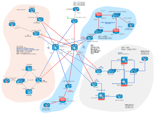
This Cisco network diagram example was drawn on the base of the figure illustrating the post "Cisco Lab 1 : Network Design from the requirement" from the blog "Thai Cisco Club".
"1. Core service porvider by assign P router as P1 and P2, PE router as PE1 - 8 for support CE router of customers.
2. From 1st customer project, assign R1-DMVPN and R2-DWVPN as DMVPN Hub, and R3-DMVPN and R4-DMVPN as DMVPN-Spoke that on different site.
3. From 2nd customer project, assign IP-SEC R1 and IP-SEC R2 as SSO-IP-SEC Router on HQ site, and IP-SEC R3 as branch site that far away."
[thai-cisco-club.blogspot.com/ 2011/ 10/ cisco-lab-1-network-design-from.html]
The diagram example "Cisco network design from the requirement" was created using the ConceptDraw PRO diagramming and vector drawing software extended with the Cisco Network Diagrams solution from the Computer and Networks area of ConceptDraw Solution Park.
Cisco network diagram
 Reflected Ceiling Plans
Reflected Ceiling Plans solution is effective tool for architects, designers, electricians, and other people which every day need convenient tool for representing their ceiling ideas. Use it to create without efforts professional Reflected Ceiling plans and Reflective Ceiling plans, showing the location of light fixtures, drywall or t-bar ceiling patterns, lighting panels, and HVAC grilles and diffusers that may be suspended from the ceiling.
 Network Layout Floor Plans
Network Layout Floor Plans solution extends ConceptDraw PRO software functionality with powerful tools for quick and efficient documentation the network equipment and displaying its location on the professionally designed Network Layout Floor Plans. Never before creation of Network Layout Floor Plans, Network Communication Plans, Network Topologies Plans and Network Topology Maps was not so easy, convenient and fast as with predesigned templates, samples, examples and comprehensive set of vector design elements included to the Network Layout Floor Plans solution. All listed types of plans will be a good support for the future correct cabling and installation of network equipment.
LLNL Flow Charts
.jpg "LLNL flow charts")
- Local network area. Computer and Network Examples | Building ...
- RCP - Computer lab | Star Network Topology | Local area network ...
- Personal area (PAN) networks . Computer and Network Examples ...
- Local area network ( LAN ). Computer and Network Examples ...
- Local area network ( LAN ). Computer and Network Examples | Hotel ...
- Computer Labs Lan Network Design
- Local area network ( LAN ). Computer and Network Examples | Star ...
- Local area network ( LAN ). Computer and Network Examples | Basic ...
- When Designing A New Computer Lab
- Local area network ( LAN ). Computer and Network Examples ...
- How To Set Up A Network Computer Lab With Server Switches And
- Network Gateway Router | Hotel Network Topology Diagram | Star ...
- Local area network ( LAN ). Computer and Network Examples ...
- Local area network ( LAN ). Computer and Network Examples | Star ...
- Local area network ( LAN ). Computer and Network Examples ...
- Network Layout Floor Plans | Local area network ( LAN ). Computer ...
- Local network area. Computer and Network Examples | Local area ...
- Local area network ( LAN ). Computer and Network Examples ...
- Local area network ( LAN ). Computer and Network Examples | Star ...
- Local area network ( LAN ). Computer and Network Examples ...