This site uses cookies. By continuing to browse the ConceptDraw site you are agreeing to our Use of Site Cookies.
"Surround sound is a technique for enriching the sound reproduction quality of an audio source with additional audio channels from speakers that surround the listener (surround channels), providing sound from a 360° radius in the horizontal plane (2D) as opposed to "screen channels" (centre, [front] left, and [front] right) originating only from the listener's forward arc.
Surround sound is characterized by a listener location or sweet spot where the audio effects work best, and presents a fixed or forward perspective of the sound field to the listener at this location. The technique enhances the perception of sound spatialization by exploiting sound localization; a listener's ability to identify the location or origin of a detected sound in direction and distance. Typically this is achieved by using multiple discrete audio channels routed to an array of loudspeakers.
There are various surround sound based formats and techniques, varying in reproduction and recording methods along with the number and positioning of additional channels." [Surround sound. Wikipedia]
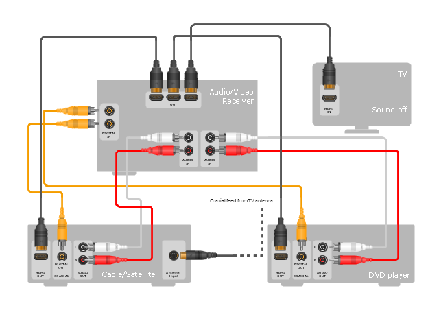
The hookup diagram example "Hook up drawing - Home entertainment system with surround sound" was created using the ConceptDraw PRO diagramming and vector drawing software extended with the Audio and Video Connectors solution from the Engineering area of ConceptDraw Solution Park.
Hookup diagram
Hookup diagram, device, half part, device, coaxial, TV, plug, connector, coaxial, TV, jack, connector, TV, RCA, phono, cinch, socket, RCA connector, RCA jack, phono connector, cinch connector, HDMI, plug, connector, HDMI, jack, connector,

Network wiring cable. Computer and Network Examples

To connect two or more network devices are used the network cables. There are more different types of the network cables: Coaxial cable, Optical fiber cable, Twisted Pair, Ethernet crossover cable, Power lines and others. They are used depending of the network topology, size, protocol.
This example was created in ConceptDraw DIAGRAM using the Computer and Networks solution from the Computer and Networks area of ConceptDraw Solution Park.

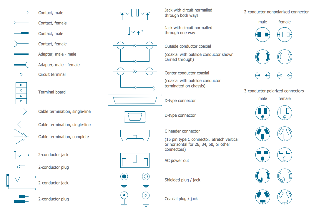
Electrical Symbols — Terminals and Connectors

An electrical connector, is an electro-mechanical device used to join electrical terminations and create an electrical circuit. Electrical connectors consist of plugs (male-ended) and jacks (female-ended). The connection may be temporary, as for portable equipment, require a tool for assembly and removal, or serve as a permanent electrical joint between two wires or devices.

26 libraries of the Electrical Engineering Solution of ConceptDraw DIAGRAM make your electrical diagramming simple, efficient, and effective. You can simply and quickly drop the ready-to-use objects from libraries into your document to create the electrical diagram.

Electrical Symbols — Delay Elements

Variable delay elements are often used to manipulate the rising or falling edges of the clock or any other signal in integrated circuits. Delay elements are also used in delay locked loops and in defining a time reference for the movement of data within those systems.

26 libraries of the Electrical Engineering Solution of ConceptDraw DIAGRAM make your electrical diagramming simple, efficient, and effective. You can simply and quickly drop the ready-to-use objects from libraries into your document to create the electrical diagram.

Electrical Symbols, Electrical Diagram Symbols

How to create Electrical Diagram? It’s very easy! All you need is a powerful software. It wasn’t so easy to create Electrical Symbols and Electrical Diagram as it is now with electrical diagram symbols offered by the libraries of Electrical Engineering Solution from the Industrial Engineering Area at the ConceptDraw Solution Park.
This solution provides 26 libraries which contain 926 electrical symbols from electrical engineering: Analog and Digital Logic, Composite Assemblies, Delay Elements, Electrical Circuits, Electron Tubes, IGFET, Inductors, Integrated Circuit, Lamps, Acoustics, Readouts, Logic Gate Diagram, MOSFET, Maintenance, Power Sources, Qualifying, Resistors, Rotating Equipment, Semiconductor Diodes, Semiconductors, Stations, Switches and Relays, Terminals and Connectors, Thermo, Transformers and Windings, Transistors, Transmission Paths,VHF UHF SHF.
The vector stencils library "Terminals and connectors" contains 43 element symbols of terminals, connectors, plugs, polarized connectors, jacks, coaxial cables, and conductors.
Use it for drawing the wiring diagrams, electrical layouts, electronic schematics, and circuit diagrams in the ConceptDraw PRO diagramming and vector drawing software extended with the Electrical Engineering solution from the Engineering area of ConceptDraw Solution Park.
www.conceptdraw.com/ solution-park/ engineering-electrical
2-conductor jack
2-conductor jack, 2-conductor, jack,
2-conductor plug
2-conductor plug, 2-conductor, plug,
2-conductor jack 2
2-conductor jack 2, 2-conductor, jack,
2-conductor plug 2
2-conductor plug 2, 2-conductor, plug,
Normalled jacks
Normalled jacks, normalled, jack, circuit,
Normalled jack
Normalled jack, normalled, jack, circuit,
Outside conductor coaxial
Outside conductor coaxial, coaxial, outside conductor,
Center conductor coaxial
Center conductor coaxial, center conductor coaxial, outside conductor, chassis,
Large D connector
Large D connector, large, D connector, D-type connector,
Small D connector
Small D connector, small, D connector, D-type connector,
C header connector
C header connector, C header connector, 15 pin, type C,
Normalled jacks
Normalled jacks, AC out, AC power out,
Сontact, male
Сontact, male, male contact,
Сontact, female
Сontact, female, female contact,
Сontact, male 2
Сontact, male 2, male contact,
Сontact, female 2
Сontact, female 2, female contact,
Adapter, male - male
Adapter, male - male, adapter, male-female,
Adapter, male - male
Adapter, male - male, adapter, male-male,
Circuit terminal
Circuit terminal, circuit terminal,
Terminal board
Terminal board, terminal board, terminal strip,
Cable termination, complete
Cable termination, complete, cable termination, complete,
Cable termination, single-line
Cable termination, single-line, cable termination, single line,
Cable termination, single-line 2
Cable termination, single-line 2, cable termination, single line,
Shielded jack
Shielded jack, shielded, RCA, jack,
Shielded plug
Shielded plug, shielded, RCA, plug,
Coaxial jack
Coaxial jack, coaxial jack,
Coaxial plug
Coaxial plug, coaxial plug,
2-conductor, male
2-conductor, male, 2-conductor, nonpolarized connector, male,
2-conductor, female
2-conductor, female, 2-conductor, nonpolarized connector, female,
2-conductor, male 2
2-conductor, male 2, 2-conductor, nonpolarized connector, male,
2-conductor, female 2
2-conductor, female 2, 2-conductor, nonpolarized connector, female,
2-conductor, male 3
2-conductor, male 3, 2-conductor, nonpolarized connector, male,
2-conductor, female 3
2-conductor, female 3, 2-conductor, nonpolarized connector, female,
3-conductor, male
3-conductor, male, 3-conductor, polarized connector, male,
3-conductor, female
3-conductor, female, 3-conductor, polarized connector, female,
3-conductor, male 2
3-conductor, male 2, 3-conductor, polarized connector, male,
3-conductor, female 2
3-conductor, female 2, 3-conductor, polarized connector, female,
3-conductor, male 3
3-conductor, male 3, 3-conductor, polarized connector, male,
3-conductor, female 3
3-conductor, female 3, 3-conductor, polarized connector, female,
3-conductor, male 4
3-conductor, male 4, 3-conductor, polarized connector, male,
3-conductor, female 4
3-conductor, female 4, 3-conductor, polarized connector, female,
3-conductor, male 5
3-conductor, male 5, 3-conductor, polarized connector, male,
3-conductor, female 5
3-conductor, female 5, 3-conductor, polarized connector, female,

Electrical Symbols — Transformers and Windings

A transformer is an electrical device that transfers electrical energy between two or more circuits through electromagnetic induction. Electromagnetic induction produces an electromotive force within a conductor which is exposed to time varying magnetic fields. Transformers are used to increase or decrease the alternating voltages in electric power applications.


26 libraries of the Electrical Engineering Solution of ConceptDraw DIAGRAM make your electrical diagramming simple, efficient, and effective. You can simply and quickly drop the ready-to-use objects from libraries into your document to create the electrical diagram.

Diagram of a Basic Computer Network. Computer Network Diagram Example

This sample was created in ConceptDraw DIAGRAM diagramming and vector drawing software using the Computer and Networks solution from Computer and Networks area of ConceptDraw Solution Park.
This sample shows the connection scheme of the home WLAN equipment to the Internet.

Multiprotocol Label Switching (MPLS). Computer and Network Examples

Multiprotocol Label Switching (MPLS) is a mechanism in high-performance telecommunication networks that implements the data transfer from one network node to another using the labels.
ConceptDraw DIAGRAM is a powerful network diagramming and vector drawing software that provides the Computer and Networks solution with wide set of ready-to-use predesigned vector stencils and examples to help you design the MPLS Networks quick and easy.

Local area network (LAN). Computer and Network Examples

A local area network (LAN) is a devices network that connect with each other in the scope of a home, school, laboratory, or office. Usually, a LAN comprise computers and peripheral devices linked to a local domain server. All network appliances can use a shared printers or disk storage. A local area network serve for many hundreds of users. Typically, LAN includes many wires and cables that demand a previously designed network diagram. They are used by IT professionals to visually document the LANs physical structure and arrangement.
ConceptDraw - Perfect Network Diagramming Software with examples of LAN Diagrams. ConceptDraw Network Diagram is ideal for network engineers and network designers who need to draw Local Area Network diagrams.
How to Draw a Computer Network