UML Use Case Diagram Example. Social Networking Sites Project

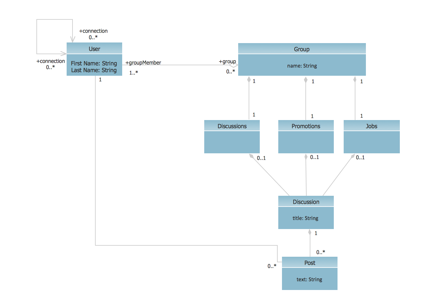
UML Class Diagram Example - Social Networking Site
 Computer Network Diagrams
Computer Network Diagrams solution extends ConceptDraw DIAGRAM software with samples, templates and libraries of vector icons and objects of computer network devices and network components to help you create professional-looking Computer Network Diagrams, to plan simple home networks and complex computer network configurations for large buildings, to represent their schemes in a comprehensible graphical view, to document computer networks configurations, to depict the interactions between network's components, the used protocols and topologies, to represent physical and logical network structures, to compare visually different topologies and to depict their combinations, to represent in details the network structure with help of schemes, to study and analyze the network configurations, to communicate effectively to engineers, stakeholders and end-users, to track network working and troubleshoot, if necessary.
 Active Directory Diagrams
Active Directory Diagrams solution significantly extends the capabilities of ConceptDraw DIAGRAM software with special Active Directory samples, convenient template and libraries of Active Directory vector stencils, common icons of sites and services, icons of LDPA elements, which were developed to help you in planning and modelling network structures and network topologies, in designing excellently looking Active Directory diagrams, Active Directory Structure diagrams, and Active Directory Services diagram, which are perfect way to visualize detailed structures of Microsoft Windows networks, Active Directory Domain topology, Active Directory Site topology, Organizational Units (OU), and Exchange Server organization.
 Entity-Relationship Diagram (ERD)
An Entity-Relationship Diagram (ERD) is a visual presentation of entities and relationships. That type of diagrams is often used in the semi-structured or unstructured data in databases and information systems. At first glance ERD is similar to a flowch
ERD Symbols and Meanings


- UML Class Diagram Example - Social Networking Site
- ConceptDraw Dashboard for Facebook | How to Create a Social ...
- Sample Use Case Diagram User And Administrator
- Use Case Diagram For Admin
- Er Diagram Of Facebook Database
- Activity Diagram Admin
- UML Sample Project | UML Use Case Diagram Example Social ...
- Sequence Diagram Social Networking
- Data Flow Diagram For Admin Login For Library
- UML Use Case Diagram Example Registration System
- UML Use Case Diagram Example Registration System | Use Case ...
- UML Use Case Diagrams
- UML Sample Project | UML Use Case Diagram Example Social ...
- Example of DFD for Online Store (Data Flow Diagram ) DFD ...
- Process Flowchart | Data Flow Diagram Symbols. DFD Library ...
- UML Use Case Diagram Example Social Networking Sites Project ...
- Flowchart | Process Flowchart | Sales Process Flowchart. Flowchart ...
- UML Sample Project | UML Use Case Diagram Example Social ...
- UML Use Case Diagram Example Social Networking Sites Project ...
- UML Sample Project | UML Use Case Diagram Example Social ...