The vector stencils library "Electrical and telecom" contains 83 symbols of electrical and telecommunication equipment for electrical drawings and wiring diagrams of buildings, communication centers, power plants and electrical distribution systems.
"An electrical drawing, is a type of technical drawing that shows information about power, lighting, and communication for an engineering or architectural project." [Electrical drawing. Wikipedia]
Use the design elements library "Electrical and telecom" to design your own electrical drawings, plot plans of the building outside electrical wiring, floor plans with electrical and telecommunication systems layout, power-riser diagrams with panel boards, control wiring diagrams and cabling layout schemes, reflected ceiling plans and lighting panels layouts using the ConceptDraw PRO diagramming and vector drawing software.
The shapes library "Electrical and telecom" is included in the Electric and Telecom Plans solution from the Building Plans area of ConceptDraw Solution Park.
Electrical and telecom symbols

The vector stencils library "Electrical and telecom" contains 83 symbols of electrical and telecommunication equipment.
Use these shapes for drawing electrical and telecom system design floor plans, cabling layout schemes, and wiring diagrams in the ConceptDraw PRO diagramming and vector drawing software.
The vector stencils library "Electrical and telecom" is included in the Electric and Telecom Plans solution from the Building Plans area of ConceptDraw Solution Park.
Luminaire ceiling mount

Enclosed ceiling luminaire

Wall light

1-light bar

2-light bar

4-light bar

6-light bar

8-light bar

Down lighter

Outdoor lightning

Outdoor lightning, bollard

Batten fluorescent, 1 lamp

Batten fluorescent, 2 lamps

Batten fluorescent, 3 lamps

Batten fluorescent, 4 lamps

Surface Fluorescent Light

Modular fluorescent fitting

Modular fluorescent fitting, inverter

Modular fluorescent fitting 2

Pull-cord switch

Emergency light

Emergency light 2

Emergency sign

Switch

Switch, 1 pole

Switch, 2 pole

Switch, 2-way

Multi-switch

Switch, intermediate

Dimmer switch

Dimmer switch 2

Socket

Socket 2

Switched socket

Switched socket 2

Double socket

Double socket 2

Socket outlet

Telephone outlet

Telephone outlet 2

Stereo outlet

Television outlet

Service panel, surface

Service panel, inset

Thermostat

Ceiling fan

Hold open unit

Detector

Fire alarm

City Fire Alarm Station

Fire Alarm Station

Fire Alarm Bell

Fire Alarm Central Station

Automatic Fire Alarm Device

Main control

Ground

Doorbell

Push Button

Buzzer

Annunciator

Horn

Maid's Signal Plug

Signal Central Station

Doorbell Chime

Doorbell Transformer

Magnetic Door Hold

Intercom

Telephone Key System

Digital Satellite System

Inside Antenna

Outside Antenna

Electric Motors

Single Phase

Three of Poly Phase

Wall Mounted Electrical Junction Box for Hardware

Wall Mounted Telephone/Data Junction Box for Hardware

Card Reader Access System

Emergency Release Button

Motion Sensor

Electric Door Opener

Watchman's Station

Watchman's Central Station

Battery

The vector stencils library "Network layout floorplan" contain 34 symbol icons for drawing computer network floor plans, communication equipment layouts, and structured cabling diagrams.
"Structured cabling is building or campus telecommunications cabling infrastructure that consists of a number of standardized smaller elements (hence structured) called subsystems. ...
Structured cabling design and installation is governed by a set of standards that specify wiring data centers, offices, and apartment buildings for data or voice communications using various kinds of cable, most commonly category 5e (CAT-5e), category 6 (CAT-6), and fibre optic cabling and modular connectors. These standards define how to lay the cabling in various topologies in order to meet the needs of the customer, typically using a central patch panel (which is normally 19 inch rack-mounted), from where each modular connection can be used as needed. Each outlet is then patched into a network switch (normally also rack-mounted) for network use or into an IP or PBX (private branch exchange) telephone system patch panel." [Structured cabling. Wikipedia]
The design elements example "Network layout floorplan - Vector stencils library" was created using the ConceptDraw PRO diagramming and vector drawing software extended with the Network Layout Floor Plans solution from the Computer and Networks area of ConceptDraw Solution Park.
PC

Scanner

Switch

Router

Modem

Hub

Rack Mount

Printer

Floor Mounted Outlet

Single Outlet

Duplex Outlet

Direct bus cable

Tops or bottoms bus cable

Side to side bus cable

Multi-tree bus cable

Bottom to side bus cable

Sides bus cable

Door

Door, threshold

Door, stop

Door, stop, threshold

Door, frame

Door, frame, threshold

Door, frame, stop

Door, frame, stop, threshold

Window

Window, sill

Window, sash

Window, sash, sill

Window, frame

Window, frame, sill

Window, frame, sash

Window, frame, sash, sill

The vector stencils library "Electrical and telecom" contains 83 symbols of electrical and telecommunication equipment.
Use these shapes for drawing electrical and telecom system design floor plans, cabling layout schemes, and wiring diagrams in the ConceptDraw PRO diagramming and vector drawing software.
The vector stencils library "Electrical and telecom" is included in the Electric and Telecom Plans solution from the Building Plans area of ConceptDraw Solution Park.
Use these shapes for drawing electrical and telecom system design floor plans, cabling layout schemes, and wiring diagrams in the ConceptDraw PRO diagramming and vector drawing software.
The vector stencils library "Electrical and telecom" is included in the Electric and Telecom Plans solution from the Building Plans area of ConceptDraw Solution Park.
Luminaire ceiling mount
Enclosed ceiling luminaire
Wall light
1-light bar
2-light bar
4-light bar
6-light bar
8-light bar
Down lighter
Outdoor lightning
Outdoor lightning, bollard
Batten fluorescent, 1 lamp
Batten fluorescent, 2 lamps
Batten fluorescent, 3 lamps
Batten fluorescent, 4 lamps
Surface Fluorescent Light
Modular fluorescent fitting
Modular fluorescent fitting, inverter
Modular fluorescent fitting 2
Pull-cord switch
Emergency light
Emergency light 2
Emergency sign
Switch
Switch, 1 pole
Switch, 2 pole
Switch, 2-way
Multi-switch
Switch, intermediate
Dimmer switch
Dimmer switch 2
Socket
Socket 2
Switched socket
Switched socket 2
Double socket
Double socket 2
Socket outlet
Telephone outlet
Telephone outlet 2
Stereo outlet
Television outlet
Service panel, surface
Service panel, inset
Thermostat
Ceiling fan
Hold open unit
Detector
Fire alarm
City Fire Alarm Station
Fire Alarm Station
Fire Alarm Bell
Fire Alarm Central Station
Automatic Fire Alarm Device
Main control
Ground
Doorbell
Push Button
Buzzer
Annunciator
Horn
Maid's Signal Plug
Signal Central Station
Doorbell Chime
Doorbell Transformer
Magnetic Door Hold
Intercom
Telephone Key System
Digital Satellite System
Inside Antenna
Outside Antenna
Electric Motors
Single Phase
Three of Poly Phase
Wall Mounted Electrical Junction Box for Hardware
Wall Mounted Telephone/Data Junction Box for Hardware
Card Reader Access System
Emergency Release Button
Motion Sensor
Electric Door Opener
Watchman's Station
Watchman's Central Station
Battery
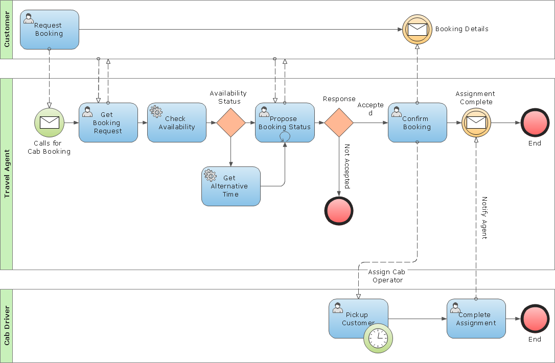
Business Process Modeling Notation Template
Network Layout


- Telecommunication Network Diagrams | Telecommunication ...
- Working Diagram Of Telephone Company
- Floor Telephone Outlet Symbol
- Ip Central Icon Vector
- Telephone Pbx Symbol
- Design elements - HVAC controls | Security system floor plan ...
- Telecommunication Symbols Wikipedia
- How To use House Electrical Plan Software | Electrical Symbols ...
- Telephone Layout Symbols
- Electrical Symbols
- Power Plant Electrical System Drawing Symbols
- Pabx Telephone System Cabling Design In A Building Plan
- Central Office Switch Icon
- Electrical Symbols , Electrical Diagram Symbols | Electrical and ...
- Telephone Tree Icon
- Telephone Layout Floorplan
- Phone networks. Computer and Network Examples | Basic ...
- Mobile Phone Diagram Symbols
- Symbol Of Electric Fitting In Building Drawing
- Electrical Symbols , Electrical Diagram Symbols | How To use House ...