How To use House Electrical Plan Software


Electrical Symbols, Electrical Diagram Symbols

Electrical Symbols — Transmission Paths
Electrical Symbols — Terminals and Connectors

Network Glossary Definition


Wiring Diagrams with ConceptDraw DIAGRAM
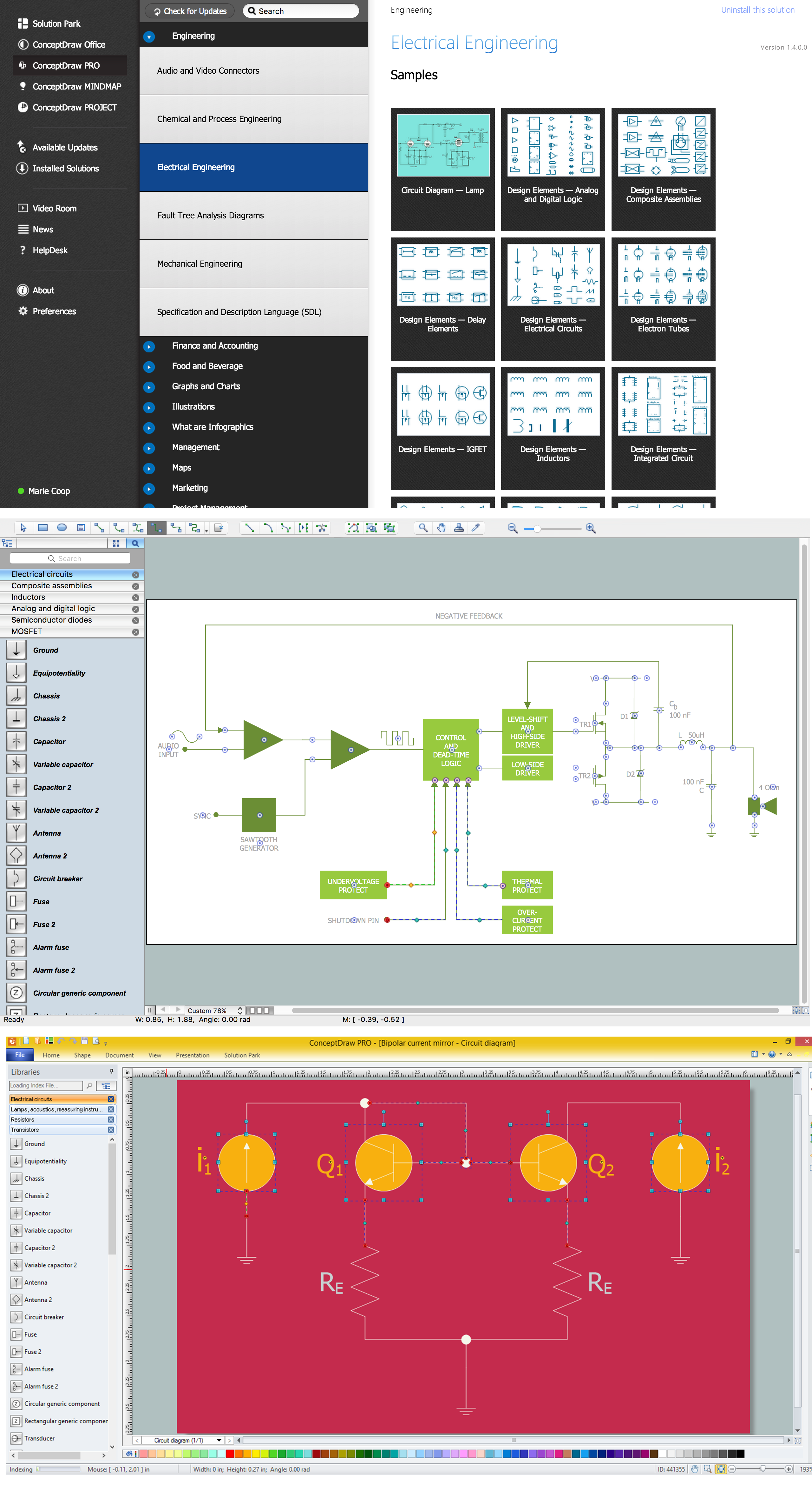
Electrical Design Software

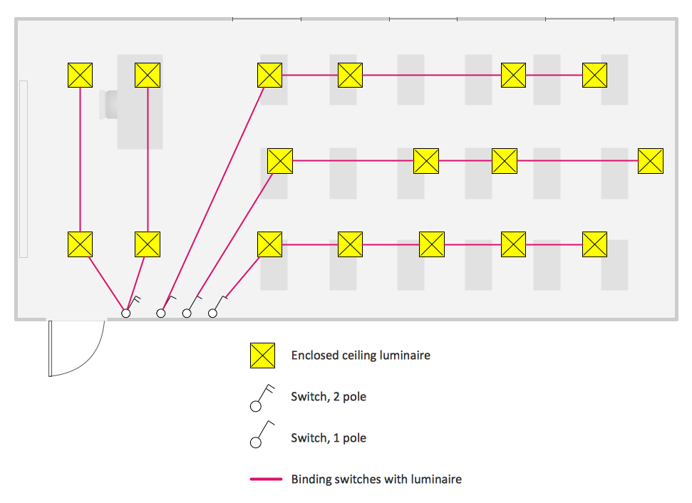
 Electric and Telecom Plans
The Electric and Telecom Plans solution providing the electric and telecom-related stencils, floor plan electrical symbols and pre-made examples is useful for electricians, interior designers, telecommunications managers, builders and other technicians when creating the electric visual plans and telecom drawings, home electrical plan, residential electric plan, telecom wireless plan, electrical floor plans whether as a part of the building plans or the independent ones.
Electrical Symbols — Switches and Relays

Electric Visual
- Catv Amplifier Circuit Diagram
- Cable Tv Node Circuit Diagram
- Amplifier - Circuit diagram | Electrical Symbols, Electrical Diagram ...
- Amplifier - Circuit diagram | Video and audio - Vector stencils library ...
- Cisco Network Templates | Cable TV - Vector stencils library ...
- Electrical Symbols, Electrical Diagram Symbols | Amplifier - Circuit ...
- Cable TV - Vector stencils library | Catv Power Supply Diagram
- Block Diagram Symbols Amplifier
- Circuits and Logic Diagram Software | Hybrid Amplifier In Optical ...