Bank Sequence Diagram

UML Sequence Diagram


Bank UML Diagram

UML Use Case Diagram Example. Services UML Diagram. ATM system

 ATM UML Diagrams
The ATM UML Diagrams solution lets you create ATM solutions and UML examples. Use ConceptDraw DIAGRAM as a UML diagram creator to visualize a banking system.
HelpDesk
How to Create a Bank ATM Use Case Diagram

UML Deployment Diagram Example - ATM System UML diagrams

UML Component for Bank

UML Collaboration Diagram. Design Elements

Flowchart on Bank. Flowchart Examples


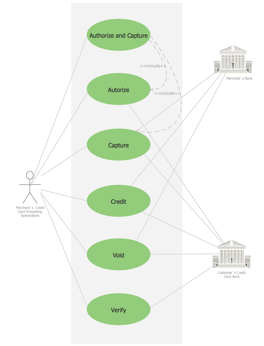
Credit Card Processing System UML Diagram
Interaction Overview Diagram

UML Diagram

UML Component Diagram

Software Diagram Examples and Templates

- Sequence Diagram For Banking System
- Intraction Diagram For Bank Transaction
- Banking System | UML use case diagram - Banking system | UML ...
- Bank Sequence Diagram | UML use case diagram - Banking system ...
- Bank Sequence Diagram | Bank UML Diagram | Banking System ...
- Draw Object Diagram For Banking Transaction System
- UML Sequence Diagram | Bank Sequence Diagram | UML ...
- Class UML Diagram for Bank Account System | Bank Sequence ...
- Bank Sequence Diagram | UML use case diagram - Banking system ...
- Banking Transaction Object Diagram
- Bank Sequence Diagram | ATM UML Diagrams | UML Sequence ...
- Bank Sequence Diagram
- Bank Sequence Diagram | UML Use Case Diagram Example ...
- Use Diagram For Bank Examples
- UML Diagram | Banking System | Bank System | User Model ...
- Bank System | Banking System | UML use case diagram - Banking ...
- Uml For Banking Transaction System Sequence Digram
- Bank Sequence Diagram
- Bank UML Diagram | How to Create a Bank ATM Use Case Diagram ...