UML Diagram

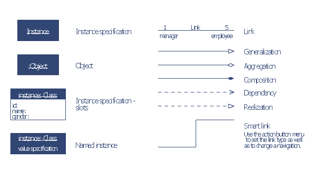
The vector stencils library "Bank UML object diagram" contains 11 shapes for drawing UML object diagrams.
Use it for object-oriented modeling of your bank information system.
"In the Unified Modeling Language (UML), an object diagram focuses on some particular set of objects and attributes, and the links between these instances. A correlated set of object diagrams provides insight into how an arbitrary view of a system is expected to evolve over time. ...
Each object and link on an object diagram is represented by an InstanceSpecification. This can show an object's classifier (e.g. an abstract or concrete class) and instance name, as well as attributes and other structural features using slots. Each slot corresponds to a single attribute or feature, and may include a value for that entity. ...
The name on an instance specification optionally shows an instance name, a ':' separator, and optionally one or more classifier names separated by commas. The contents of slots, if any, are included below the names, in a separate attribute compartment. A link is shown as a solid line, and represents an instance of an association. ...
An object instance may be called an instance specification or just an instance. A link between instances is generally referred to as a link. Other UML entities, such as an aggregation or composition symbol (a diamond) may also appear on an object diagram." [Object diagram. Wikipedia]
This example of UML object diagram symbols for the ConceptDraw PRO diagramming and vector drawing software is included in the ATM UML Diagrams solution from the Software Development area of ConceptDraw Solution Park.
UML object diagram symbols
Create UML Diagram
 Entity-Relationship Diagram (ERD)
Entity-Relationship Diagram (ERD) solution extends ConceptDraw DIAGRAM software with templates, samples and libraries of vector stencils from drawing the ER-diagrams by Chen's and crow’s foot notations.
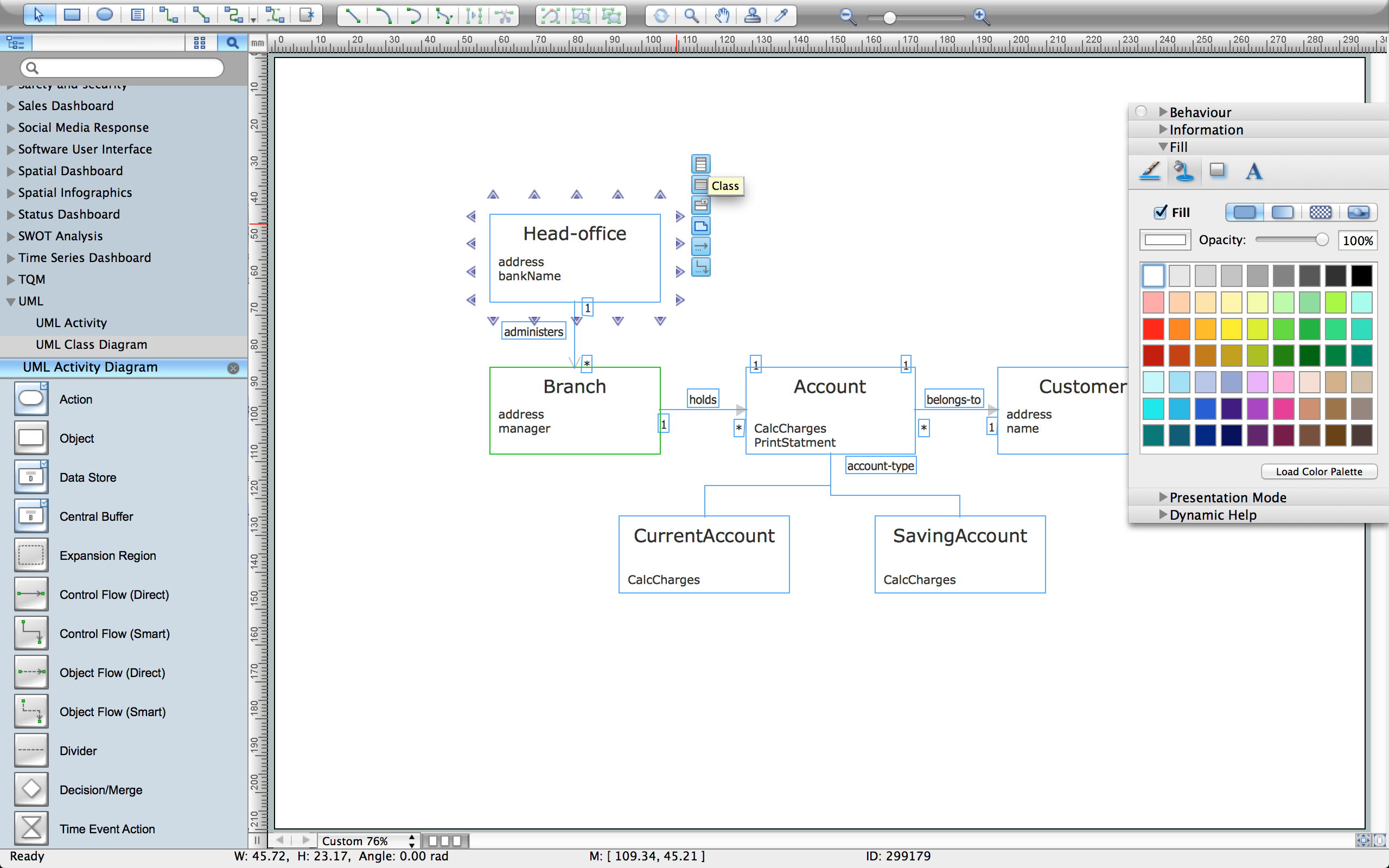
The vector stencils library "Bank UML class diagram" contains 19 shapes for drawing UML class diagrams.
Use it for object-oriented modeling of your bank information system.
"The class diagram is the main building block of object oriented modelling. It is used both for general conceptual modelling of the systematics of the application, and for detailed modelling translating the models into programming code. Class diagrams can also be used for data modeling. The classes in a class diagram represent both the main objects, interactions in the application and the classes to be programmed.
In the diagram, classes are represented with boxes which contain three parts:
* The top part contains the name of the class. It is printed in bold and centered, and the first letter is capitalized.
* The middle part contains the attributes of the class. They are left-aligned and the first letter is lowercase.
* The bottom part contains the methods the class can execute. They are also left-aligned and the first letter is lowercase.
In the design of a system, a number of classes are identified and grouped together in a class diagram which helps to determine the static relations between those objects. With detailed modelling, the classes of the conceptual design are often split into a number of subclasses." [Class diagram. Wikipedia]
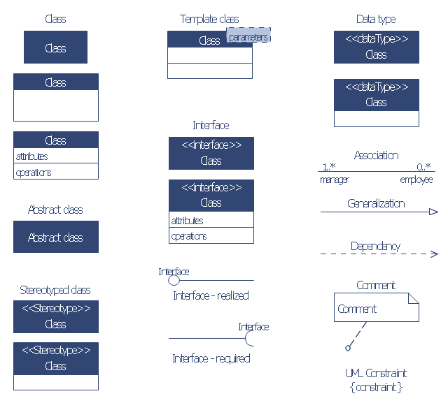
This example of UML class diagram symbols for the ConceptDraw PRO diagramming and vector drawing software is included in the ATM UML Diagrams solution from the Software Development area of ConceptDraw Solution Park.
Use it for object-oriented modeling of your bank information system.
"The class diagram is the main building block of object oriented modelling. It is used both for general conceptual modelling of the systematics of the application, and for detailed modelling translating the models into programming code. Class diagrams can also be used for data modeling. The classes in a class diagram represent both the main objects, interactions in the application and the classes to be programmed.
In the diagram, classes are represented with boxes which contain three parts:
* The top part contains the name of the class. It is printed in bold and centered, and the first letter is capitalized.
* The middle part contains the attributes of the class. They are left-aligned and the first letter is lowercase.
* The bottom part contains the methods the class can execute. They are also left-aligned and the first letter is lowercase.
In the design of a system, a number of classes are identified and grouped together in a class diagram which helps to determine the static relations between those objects. With detailed modelling, the classes of the conceptual design are often split into a number of subclasses." [Class diagram. Wikipedia]
This example of UML class diagram symbols for the ConceptDraw PRO diagramming and vector drawing software is included in the ATM UML Diagrams solution from the Software Development area of ConceptDraw Solution Park.
UML class diagram symbols
 Venn Diagrams
Venn Diagrams are actively used to illustrate simple set relationships in set theory and probability theory, logic and statistics, mathematics and computer science, linguistics, sociology, and marketing. Venn Diagrams are also often used to visually summarize the status and future viability of a project.
 PM Easy
PM Easy solution extends the ConceptDraw PROJECT functionality with an ability to support neutral methodology of project management and to quickly start a project by listing the task relationships and dependencies, that makes the iterative planning much easier. The project management tool and available visual tools, such as mind mapping, increase the effectiveness of tracking and analysis your project tasks. PM Easy solution from ConceptDraw Solution Park is mainly targeted at project managers in small or medium-sized companies, allowing them to make the project plan and execute projects using mind mapping technique, to implement planning using mind mapping, and to track tasks using ConceptDraw PROJECT application.
 PM Planning
The PM Planning solution extends the functional abilities of ConceptDraw MINDMAP and ConceptDraw PROJECT software, allowing to automatically create the spreadsheets reflecting the tasks and project statuses for people who have different project roles. The reporting capabilities of this solution are represented by the possibility to generate a wide range of project reports that allow the project managers, senior management and other project participants to be informed on a project daily progress and monthly objectives: All Inclusive Report, All Visible Columns, Milestones with Notes and Objectives, Projects Goals, Projects Managers, Project Team, and Top Level Tasks. The PM Planning solution from ConceptDraw Solution Park is a strong project management and productivity tool which simplifies the process of reporting and lets one create a document with the desired report, includes the predesigned examples, extends and improves the planning capabilities for all team members, improves the project communication, helps to accurately plan, maintain, and finish projects on time, to track the work of project resources, to perform the analytical work and to make effective decisions.
Software and Database Design with ConceptDraw DIAGRAM

- UML Use Case Diagrams | UML use case diagram - Banking system
- Banking System Uml Diagram Free Download
- UML Diagram | UML for Bank | Create UML Diagram | Class ...
- UML Package Diagram | Diagramming Software for Design UML ...
- Package Diagram With Example In Banking System Model
- Network Architecture | Create UML Diagram | UML for Bank ...
- UML Diagram | UML for Bank | UML Component for Bank | Activity ...
- UML Class Diagram Example for Transport System | UML Class
- UML Component for Bank | UML Deployment Diagram Example ...
- UML for Bank
- UML use case diagram - Banking system
- UML Diagrams with ConceptDraw PRO | UML Class Diagrams ...
- How To Create Class Diagram In Uml Using Concept
- UML Class Diagrams. Diagramming Software for Design UML ...
- UML for Bank | UML Use Case Diagram Example. Services UML ...
- UML Component for Bank | Rapid UML | UML Deployment Diagram ...
- UML Deployment Diagram Example - ATM System | UML Diagram ...
- Class Diagram Uml Template
- UML Diagram
- UML Class Diagrams. Diagramming Software for Design UML ...