"The symbols and conventions used in welding documentation are specified in national and international standards such as ISO 2553 Welded, brazed and soldered joints -- Symbolic representation on drawings and ISO 4063 Welding and allied processes -- Nomenclature of processes and reference numbers. The US standard symbols are outlined by the American National Standards Institute and the American Welding Society and are noted as "ANSI/ AWS".
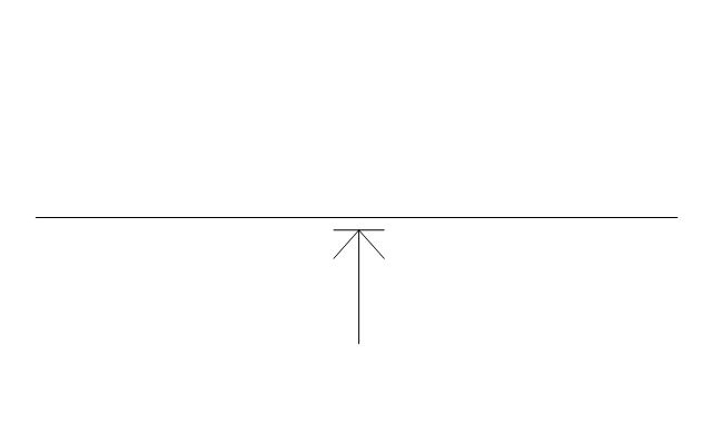
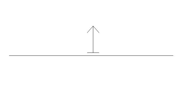
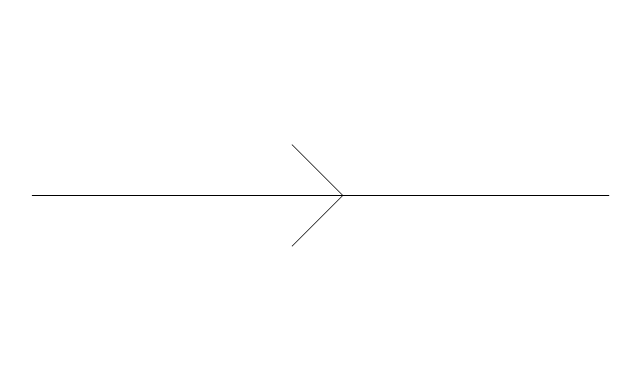
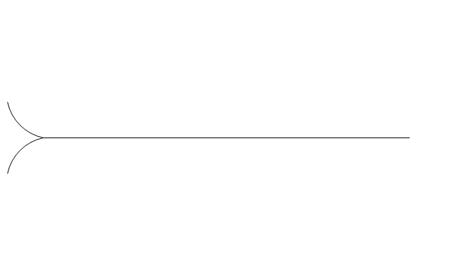
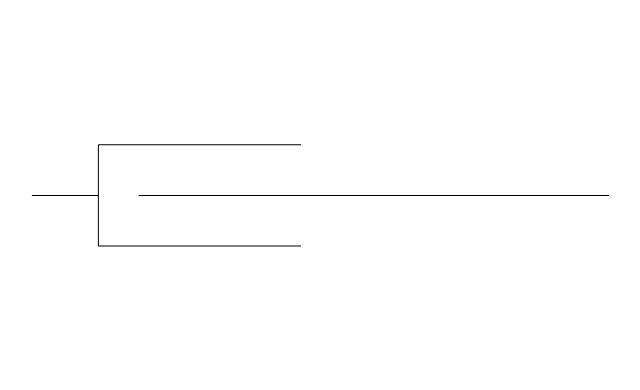
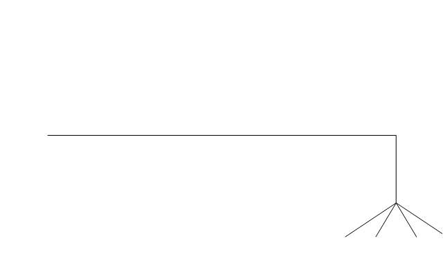
In engineering drawings, each weld is conventionally identified by an arrow which points to the joint to be welded. The arrow is annotated with letters, numbers and symbols which indicate the exact specification of the weld. In complex applications, such as those involving alloys other than mild steel, more information may be called for than can comfortably be indicated using the symbols alone. Annotations are used in these cases." [Symbols and conventions used in welding documentation. Wikipedia]
The example chart "Elements of welding symbol" is redesigned using the ConceptDraw PRO diagramming and vector drawing software from the Wikipedia file: Elements of a welding symbol.PNG.
[en.wikipedia.org/ wiki/ File:Elements_ of_ a_ welding_ symbol.PNG]
The diagram example "Elements location of a welding symbol" is contained in the Mechanical Engineering solution from the Engineering area of ConceptDraw Solution Park.
Welding joint symbol chart

Mechanical Drawing Symbols

The vector stencils library "Welding" contains 38 welding joint symbols to identify fillets, contours, resistance seams, grooves, surfacing, and backing.
Use it to indicate welding operations on working drawings in the ConceptDraw PRO diagramming and vector drawing software extended with the Mechanical Engineering solution from the Engineering area of ConceptDraw Solution Park.
www.conceptdraw.com/ solution-park/ engineering-mechanical
Use it to indicate welding operations on working drawings in the ConceptDraw PRO diagramming and vector drawing software extended with the Mechanical Engineering solution from the Engineering area of ConceptDraw Solution Park.
www.conceptdraw.com/ solution-park/ engineering-mechanical
Additional arrow
Text block

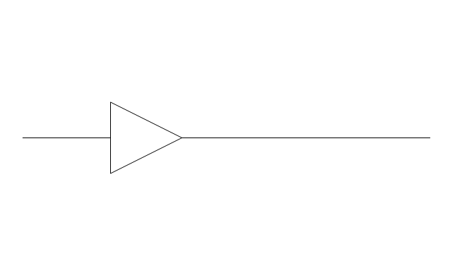
Fillet

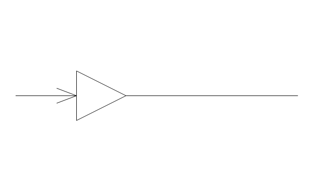
Slot / plug

Stud

Resistance seam

Backing

Surfacing

Flange corner

Flange edge

Square groove

V-groove

Bevel groove

U-groove

J-groove

Flare V groove

Flare bevel groove

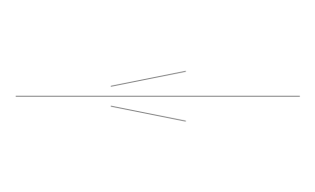
Scarf

Melt through weld

Field weld

Backing / spacer

Insert

Arrow with bend
Arrow with bend, tail
Arrow with bend, circle
Arrow with bend, circle, tail
Arrow
Arrow, tail

Arrow, circle

Arrow, circle, tail

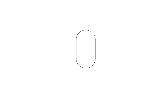
Spot

Projection weld

Contour, concave

Contour, convex

Contour, flush

Contour angled, concave

Contour angled, convex

Contour angled, flush

Square butt weld

Closed square butt weld

Single-bevel butt weld

Double-bevel butt weld

Single-V butt weld

Double-V butt weld

Single-J butt weld

Double-J butt weld

Single-U butt weld

Double-U butt weld

Flange butt weld

Tee butt weld

Flare butt weld

Square butt joint

Single V preparation joint

Lap joint

T-joint

Butt weld

Butt weld, single-V

Bilateral lap weld

Tee weld

Angular weld

Mechanical weld

The vector stencils library "Valve assembly" contains 141 symbols of pressure and flow regulators, flow direction indicators, controls, and symbols to design flow paths of control valves.
Use these valve assembly shapes to design the engineering drawings of hydraulic and pneumatic valve assemblies in fluid power systems.
"Control valves are valves used to control conditions such as flow, pressure, temperature, and liquid level by fully or partially opening or closing in response to signals received from controllers that compare a "setpoint" to a "process variable" whose value is provided by sensors that monitor changes in such conditions.
The opening or closing of control valves is usually done automatically by electrical, hydraulic or pneumatic actuators. Positioners are used to control the opening or closing of the actuator based on electric, or pneumatic signals.
A control valve consists of three main parts in which each part exist in several types and designs: Valve's actuator, Valve's positioner, Valve's body.
" [Control valves. Wikipedia]
The shapes example "" was created using the ConceptDraw PRO diagramming and vector drawing software extended with the Mechanical Engineering solution from the Engineering area of ConceptDraw Solution Park.
Valve assembly symbols

 Mechanical Engineering
This solution extends ConceptDraw DIAGRAM.9 mechanical drawing software (or later) with samples of mechanical drawing symbols, templates and libraries of design elements, for help when drafting mechanical engineering drawings, or parts, assembly, pneumatic,
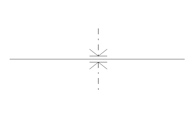
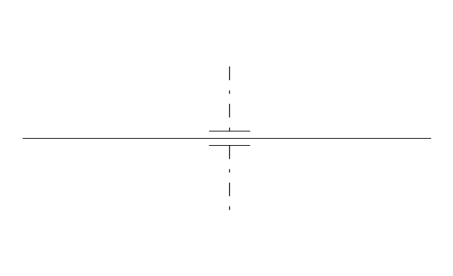
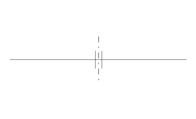
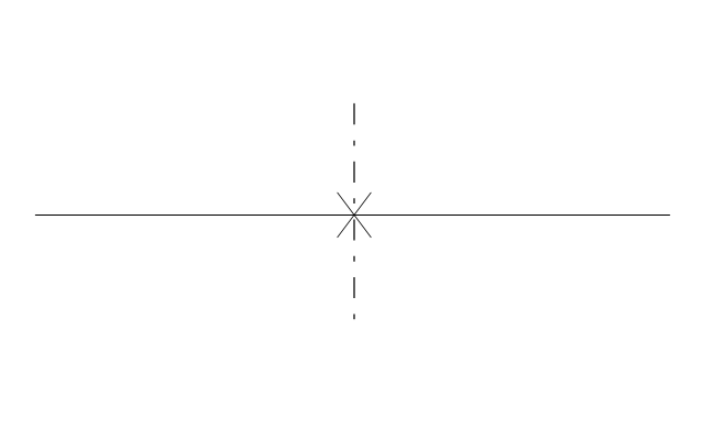
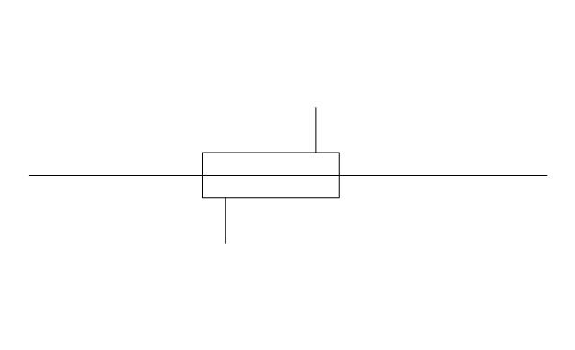
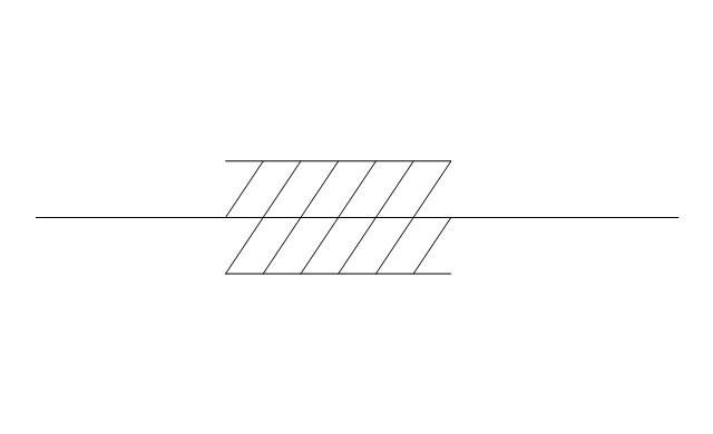
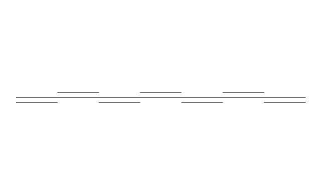
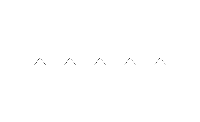
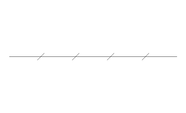
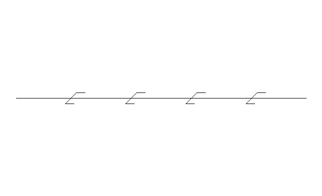
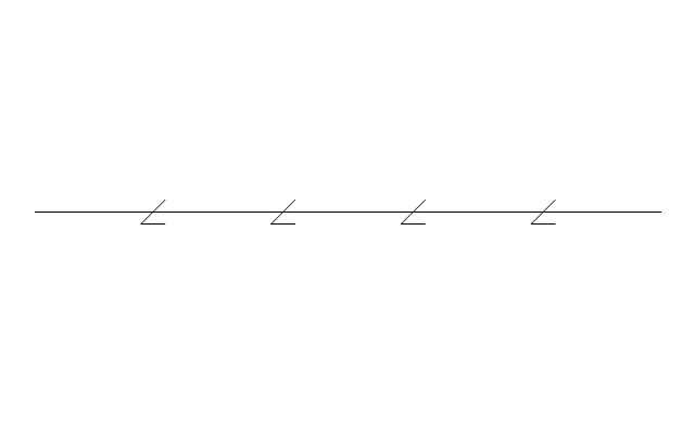
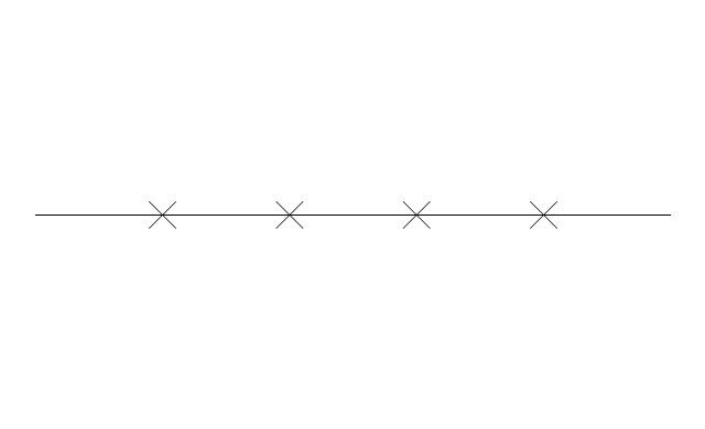
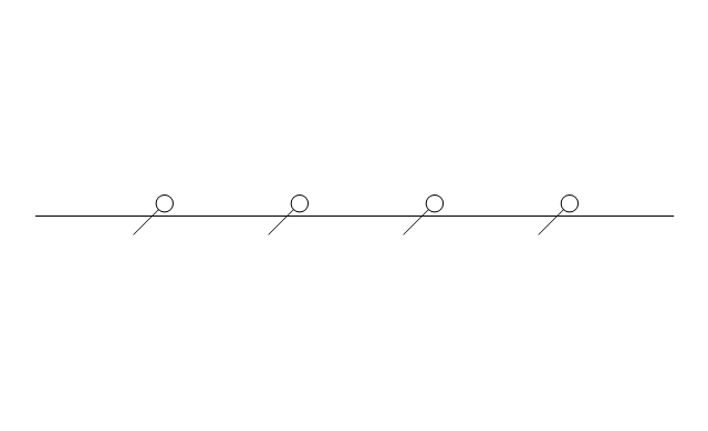
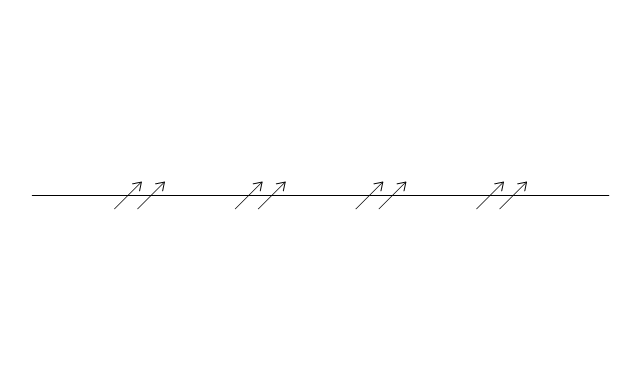
This engineering drawing present weld type symbols and fillet weld symbols.
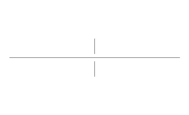
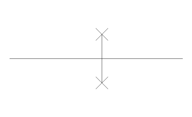
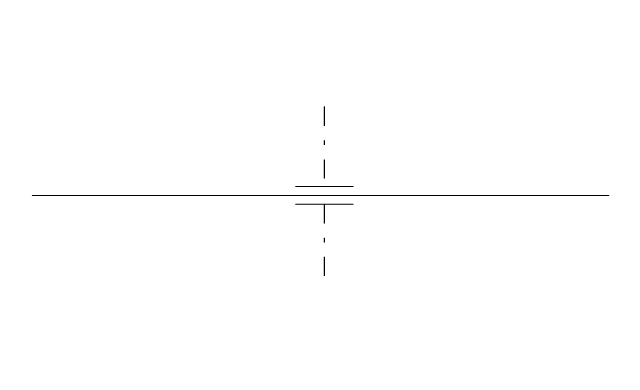
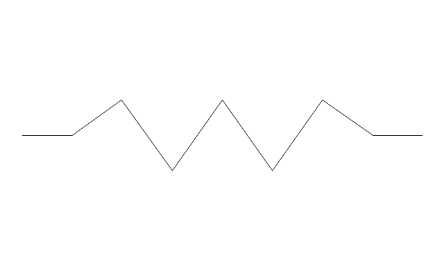
The weld type symbol is typically placed above or below the center of the reference line, depending on which side of the joint it's on. The symbol is interpreted as a simplified cross-section of the weld.
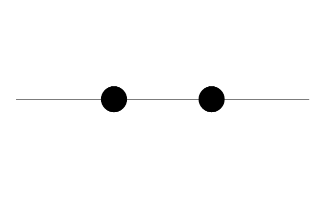
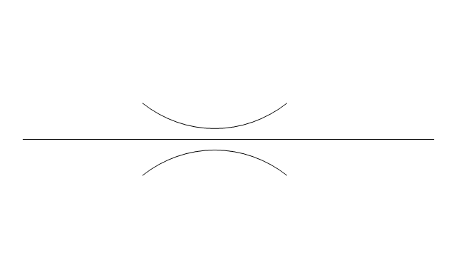
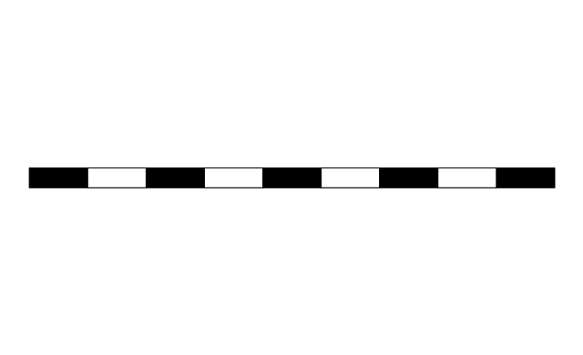
"Fillet welding refers to the process of joining two pieces of metal together whether they be perpendicular or at an angle. These welds are commonly referred to as Tee joints which are two pieces of metal perpendicular to each other or Lap joints which are two pieces of metal that overlap and are welded at the edges. The weld is aesthetically triangular in shape and may have a concave, flat or convex surface depending on the welder’s technique. Welders use fillet welds when connecting flanges to pipes, welding cross sections of infrastructure, and when fastening metal by bolts isn't strong enough." [Fillet weld. Wikipedia]
The engineering drawing example Welding symbols is included in the Mechanical Engineering solution from Engineering area of ConceptDraw Solution Park.
The weld type symbol is typically placed above or below the center of the reference line, depending on which side of the joint it's on. The symbol is interpreted as a simplified cross-section of the weld.
"Fillet welding refers to the process of joining two pieces of metal together whether they be perpendicular or at an angle. These welds are commonly referred to as Tee joints which are two pieces of metal perpendicular to each other or Lap joints which are two pieces of metal that overlap and are welded at the edges. The weld is aesthetically triangular in shape and may have a concave, flat or convex surface depending on the welder’s technique. Welders use fillet welds when connecting flanges to pipes, welding cross sections of infrastructure, and when fastening metal by bolts isn't strong enough." [Fillet weld. Wikipedia]
The engineering drawing example Welding symbols is included in the Mechanical Engineering solution from Engineering area of ConceptDraw Solution Park.
Welding joint symbols

The vector stencils library "Pipes 2" contains 48 symbols of pipes. Use it for drawing plumbing and piping building plans, schematic diagrams, blueprints, or technical drawings of waste water disposal systems, hot and cold water supply systems in the ConceptDraw PRO diagramming and vector drawing software extended with the Plumbing and Piping Plans solution from the Building Plans area of ConceptDraw Solution Park.
Crossing
Junction
Basic support
Guide 1
Guide 2
Guide 3
Stopper
Anchor
Support / anchor
Hunger
Cross
Double branch
Jacketed
Sleeved
Sleeve joint
Expansion sleeve joint
Lagged
Bellows
Flow indication
Flow indication 2
Reducer
Reducer,arrow
Pipe bore change
Flexibility provision
Sleeve extension
Flow restrictor
Elbow 45
Elbow 90
Heated or cooled
Pneumatic line
Signal line
Electric line
Hydraulic line
Capillary line
Internal connection
Route radiation
Mechanical linkage
Electrical device
Vibratory device
Weight device
Spray device
Rotary motion
Stirring / fan
Access points
Trap
Expansion loop
Flexible hose
Flexible hose, flanged
Electrical Symbols — Switches and Relays

Mechanical Engineering

The vector stencils library "Valve assembly" contains 141 symbols of pressure and flow regulators, flow direction indicators, controls, and symbols to design flow paths of control valves.
Use these valve assembly shapes to design the engineering drawings of hydraulic and pneumatic valve assemblies in fluid power systems.
"Control valves are valves used to control conditions such as flow, pressure, temperature, and liquid level by fully or partially opening or closing in response to signals received from controllers that compare a "setpoint" to a "process variable" whose value is provided by sensors that monitor changes in such conditions.
The opening or closing of control valves is usually done automatically by electrical, hydraulic or pneumatic actuators. Positioners are used to control the opening or closing of the actuator based on electric, or pneumatic signals.
A control valve consists of three main parts in which each part exist in several types and designs: Valve's actuator, Valve's positioner, Valve's body.
" [Control valves. Wikipedia]
The shapes example "" was created using the ConceptDraw PRO diagramming and vector drawing software extended with the Mechanical Engineering solution from the Engineering area of ConceptDraw Solution Park.
Use these valve assembly shapes to design the engineering drawings of hydraulic and pneumatic valve assemblies in fluid power systems.
"Control valves are valves used to control conditions such as flow, pressure, temperature, and liquid level by fully or partially opening or closing in response to signals received from controllers that compare a "setpoint" to a "process variable" whose value is provided by sensors that monitor changes in such conditions.
The opening or closing of control valves is usually done automatically by electrical, hydraulic or pneumatic actuators. Positioners are used to control the opening or closing of the actuator based on electric, or pneumatic signals.
A control valve consists of three main parts in which each part exist in several types and designs: Valve's actuator, Valve's positioner, Valve's body.
" [Control valves. Wikipedia]
The shapes example "" was created using the ConceptDraw PRO diagramming and vector drawing software extended with the Mechanical Engineering solution from the Engineering area of ConceptDraw Solution Park.
Valve assembly symbols
- Drawing Signs And Symbols Arrow Means In Engineering
- Electrical Symbols , Electrical Diagram Symbols | Circle With Arrow ...
- Mechanical Drawing Symbols | Welding - Vector stencils library ...
- Welding - Vector stencils library | Welding symbols | Welding ...
- Electrical Symbols — Terminals and Connectors | Mechanical ...
- Welding symbols | Elements location of a welding symbol | Design ...
- Mechanical Engineering | Butt weld geometry | Welding symbols ...
- Elements location of a welding symbol | Mechanical Drawing ...
- Butt weld geometry | Mechanical Engineering | Welding symbols ...
- Welding symbols | Design elements - Welding | Mechanical ...